00198150-02_SM_TX_en.pdf - 第18页
1 Introduction 1.3 Other Instructions 18 Service Manual SIPLACE TX Series 06/2017 1.3.4.3 Handling ESD Modules Do not touch electronic modules unless it is absolutely essential to do so in order to carry out other work. …
1 Introduction
1.3 Other Instructions
Service Manual SIPLACE TX Series 06/2017 17
1.3 Other Instructions
1.3.1 Environmentally-Friendly Disposal of Materials and Components
SIPLACE products are manufactured using only materials and parts that can be easily separated
and disposed of in an environmentally-friendly way.
NOTICE
Observe the applicable regulations
The company operating the system has sole responsibility for the proper, environmentally-
friendly disposal of machines, working materials, consumables and wear parts.
► Please observe your national statutory provisions for waste disposal and environ-
mental protection.
1.3.2 Use of Original SIPLACE Accessories and Spare Parts
Only use original spare parts and authorized accessories. The use of other parts will affect safety
and will invalidate the liability for any consequential damage.
1.3.3 Information About This Service Manual
WARNING
Additional qualifications required
The service work described in this manual may only be performed by specially trained ser-
vice technicians, with appropriate qualifications and expertise.
If you should have any questions during the service work, please contact the SIPLACE customer
hotline directly or send an e-mail to hotline.siplace@asmpt.com.
1.3.4 ESD Guidelines
1.3.4.1 Definition of ESD
Almost all of the modules in use today are equipped with highly integrated MOS blocks and com-
ponents. The manufacturing techniques used mean that these electronic components are ex-
tremely sensitive to overvoltage and thus to electrostatic discharge.
Fig.5: ESD label
The abbreviation for such modules is "ESD"(Electrostatic Sensitive
Device). This is used internationally, although the German abbreviation
"EGB" may also be seen. The following symbol on cabinet rating plates,
racks or packaging indicates that components which are sensitive to elec-
trostatic discharge have been used and thus that the modules concerned
are also touch-sensitive.
ESDs can be destroyed by voltages and electrostatic charges that are far below the level that can
be perceived by humans. Such voltages occur if a person touches a component or module
without earthing themselves. Components that are exposed to such overvoltage do not generally
appear to be defective immediately - incorrect behavior starts after the component or module has
been in operation for some time.
1.3.4.2 Important Measures to Protect Against Static Charging
► Most plastics can easily become charged and must therefore be kept away from at-risk com-
ponents.
► Always ensure that people, the workplace and packaging are safely earthed when handling
electrostatic sensitive components.

1 Introduction
1.3 Other Instructions
18 Service Manual SIPLACE TX Series 06/2017
1.3.4.3 Handling ESD Modules
Do not touch electronic modules unless it is absolutely essential to do so in order to carry out other
work. If it is necessary, make sure that you do not touch the pins or printed conductors when you
pick up flat modules.
Do not touch components unless
●
You are constantly earthed by an ESD wrist strap or
●
You are wearing ESD shoes or ESD shoe earthing strips on an ESD floor.
Always discharge yourself before you touch an electronic module. To do this, simply touch a con-
ductive and earthed object immediately before you touch the module (such as unpainted parts of a
switch cabinet, a water pipe, etc.).
Do not allow modules with chargeable and highly insulating materials to touch one another, e.g.
plastic films, insulating table surfaces or items of clothing made from synthetic fibers.
Always place the modules on a conductive surface (table with an ESD coating, conductive ESD
foam, ESD bag or container).
Do not bring modules near visual display units, monitors or televisions. Keep them at least 10cm
away from the screen.
1.3.4.4 Measurements and Modifications to ESD Modules
Measurements of the assemblies may only be taken if
●
The measuring device has been grounded (e.g. via protective conductor) or
●
you discharge the measuring head before taking measurements with a potential-free measur-
ing device (e.g. by touching an unpainted metal part of the controller casing).
► Always use an earthed soldering iron if you carry out any soldering work.
1.3.4.5 Dispatching ESD Modules
► Always store modules and components in conductive packaging (e.g. metalized plastic bags
or metal sleeves) and dispatch them in conductive packaging.
► If the packaging is not conductive, place the modules in a conductive envelope before pack-
aging. Use conductive expanded rubber, ESD bags, domestic aluminum foil or paper, for ex-
ample.
► If the module has integral batteries, ensure that the conductive packaging does not touch or
short-circuit the battery terminals and, if necessary, first cover the terminals with insulating
tape or material.
1.3.5 Validity of Document
This document is valid for the following machine types:
●
SIPLACE TX Series
The work described in this manual is divided into modules, and to a large extent, it is identical for
all machine types:
●
If the work required for specific machines differs from the standard procedure, this will be in-
dicated with reference to the machine number, series and delivery state.
●
Illustrations are only shown as examples, for example, the illustration of a specific machine
type or a machine with different paint finish does not imply that the information following the il-
lustration only applies to the shown machine type.
Please read the circuit diagram folder for any electrical checks.
●
Detailed circuit diagrams folder for SIPLACE TX-Series (up to no. 499) [DE+EN: 00197933-
xx]
●
Detailed circuit diagrams folder for SIPLACE TX-Series (from no. 500) [DE+EN: 00198274-xx]
1 Introduction
1.3 Other Instructions
Service Manual SIPLACE TX Series 06/2017 19
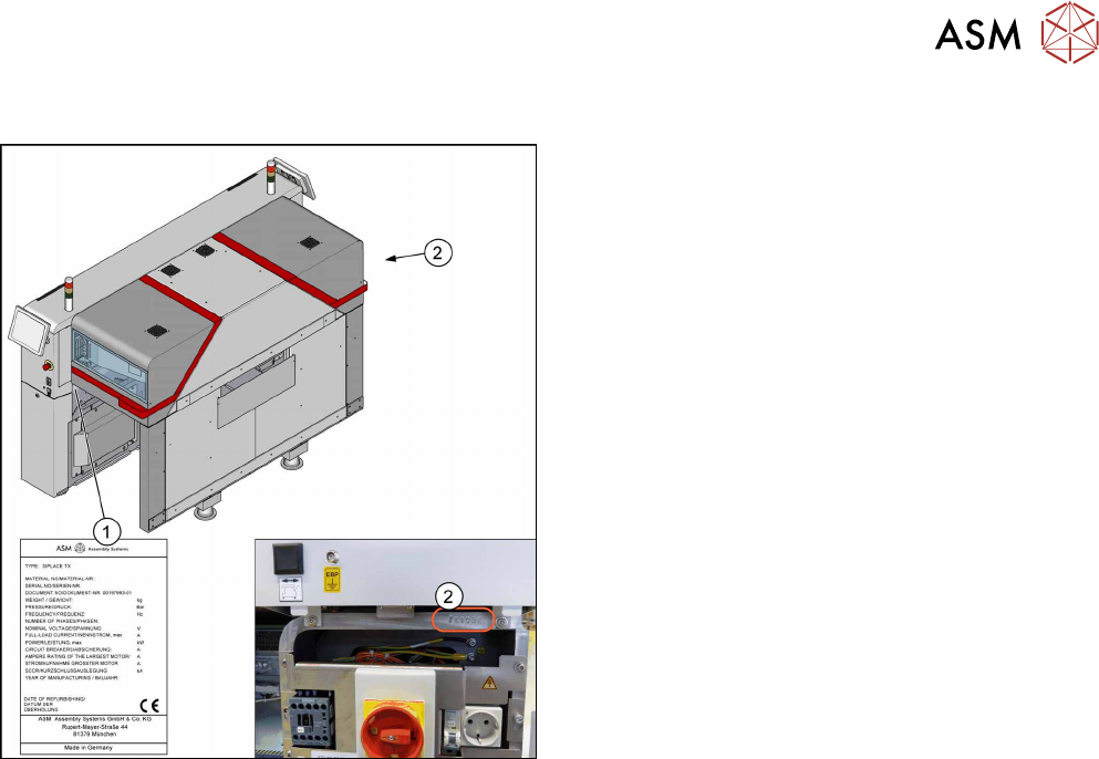
1.3.6 Serial Number of the Machine
Fig.6: Serial number
The serial number of the machine can be found in two
places.
1. On the typeplate on the inside of the machine
frame at location1.
2. Above the main switch at location 2 behind the
cover.