00198150-02_SM_TX_en.pdf - 第190页
7 Conveyor 7.8 Setting the Fixed Conveyor Rail 190 Service Manual SIPLACE TX Series 06/2017 7.8.1 Conveyor Rails - Settings The following diagram shows a conveyor with the fixed conveyor side on the right. The same set- …
7 Conveyor
7.8 Setting the Fixed Conveyor Rail
Service Manual SIPLACE TX Series 06/2017 189
The conveyor sides are fixed with fastening screws:
●
Two fastening screws for standard conveyor
●
Three fastening screws if "Input/output extension" option is installed
Adjustment
► Use the software or manually move the conveyor rail into a position which allows you best ac-
cess.
– To move the conveyor rail manually, pull the toothed belt of the width adjustment unit.
► Switch off the machine, disconnect it from the power supply and secure it to prevent
unauthorized reactivation. Observe the instructions in section 1.2 "Preparatory Work..." [}15].
► Move all gantries out of the transport area as far as possible at one side of the machine.
► Always perform the following three steps immediately.
► Remove the two screws fastening the conveyor side.
► Move the conveyor side into the required position.
► Insert the screws loosely. Press the side wall so that it engages with the screw holes either in
a forwards or backwards inclination (against two screws in the same direction). Tighten the
fastening screws in the new position.
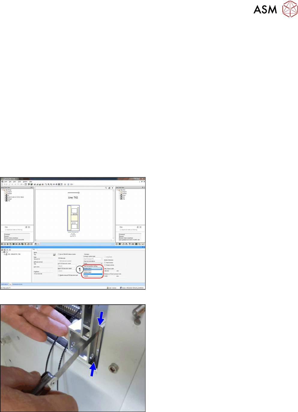
Fig.253: Settings in SIPLACE Pro
► (1) Set the fixed conveyor side and the position in
SIPLACE Pro.
► Accept the new configuration in station software
when first downloading it from SIPLACE Pro.
Fig.254: Adjusting the distance
► If you loosened the conveyor sides, fix them now.
If a conveyor side is in the outmost position, you
must set the distance between the side and the
holding bracket to 0.25mm using a feeler gauge.
7 Conveyor
7.8 Setting the Fixed Conveyor Rail
190 Service Manual SIPLACE TX Series 06/2017
7.8.1 Conveyor Rails - Settings
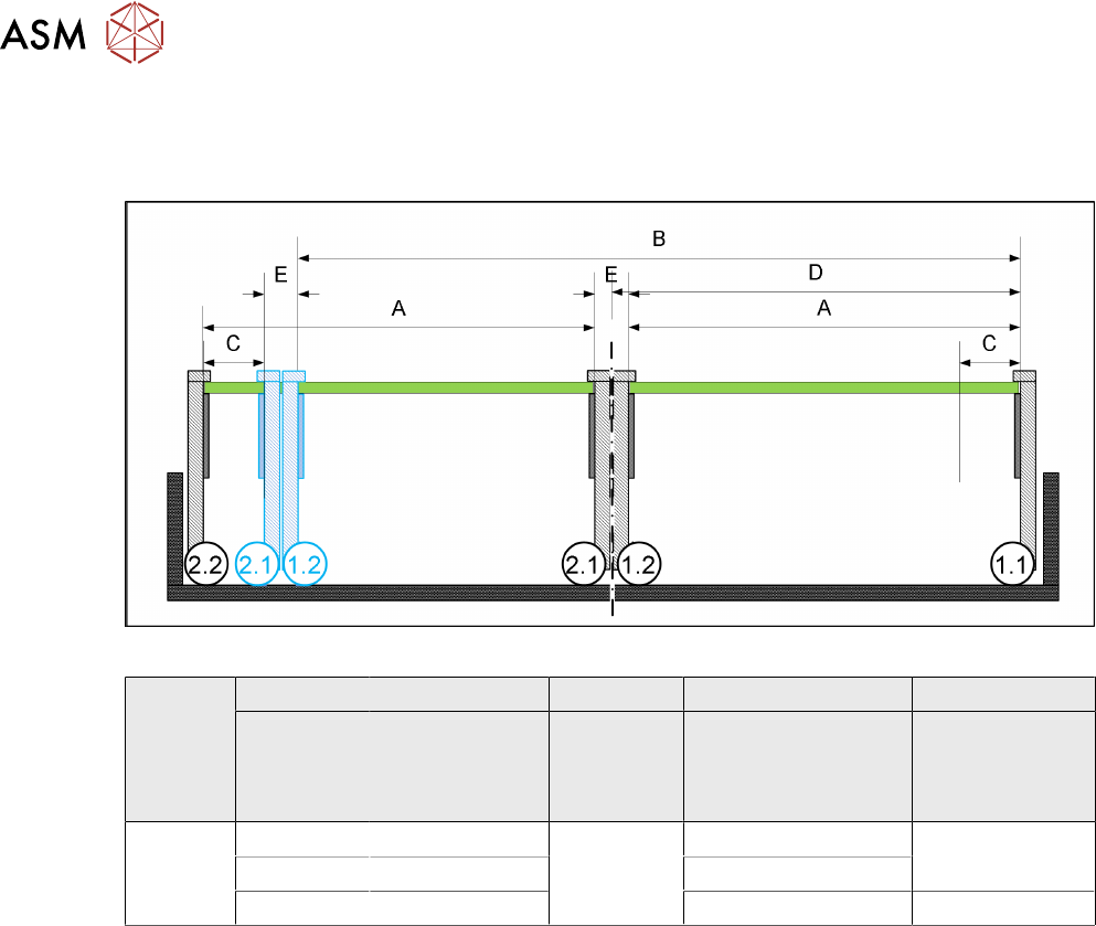
The following diagram shows a conveyor with the fixed conveyor side on the right. The same set-
tings apply to conveyors with the fixed side on the left.
Fig.255: View of a conveyor with a fixed side on the right (SIPLACE X-Series S as example)
SIPLACE
TX-
Series
A B C D E
Maximum
PCB width
Dual as single
conveyor
(flex)
Minimum
PCB width
Position of fixed
conveyor side
(from the
conveyor center)
Minimum
side wall dis-
tance
Side wall 1.2/2.1
Dual con-
veyor
236 433 45 mm 231 45 mm
250 450 268
260 460 281 35 mm
7 Conveyor
7.9 Checking Parallelism of Conveyor Rails
Service Manual SIPLACE TX Series 06/2017 191
7.9 Checking Parallelism of Conveyor Rails
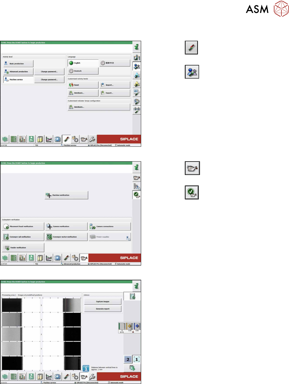
Fig.256: Select operator level
► Click the
button to enter the Settings
menu.
► Click the
button to open the Check and set
user settings menu.
► Switch to operator level Machine service or bet-
ter.
Fig.257: Maintenance menu
► Click the
button to enter the maintenance
menu.
► Click the
button.
► Click the Conveyor rail verification button.
Fig.258: Conveyor rail verification
► Click the Capture images button to run check.
► Click the Generate report button to view details.