00198150-02_SM_TX_en.pdf - 第210页
8 Placement Heads and Stationary Cameras 8.4 Replacing the SIPLACE TwinHead 210 Service Manual SIPLACE TX Series 06/2017 Conversion to another installation height Fig.287: Conversion 1. Hole for the fastening screw of t…
8 Placement Heads and Stationary Cameras
8.3 Replacing the SIPLACE CPP/M Head
Service Manual SIPLACE TX Series 06/2017 209
8.3.1 Preparing the CPP Head for the Installation Height
CAUTION
Different heights
The placement head can be installed at two different heights. CPP_L corresponds to a
component height of sixmm. CPP_H corresponds to a component height of 11.5mm.
If the CPP head is used in a placement area with stationary camera, TwinHead or JTF, it
may only be used in the upper position.
Overview
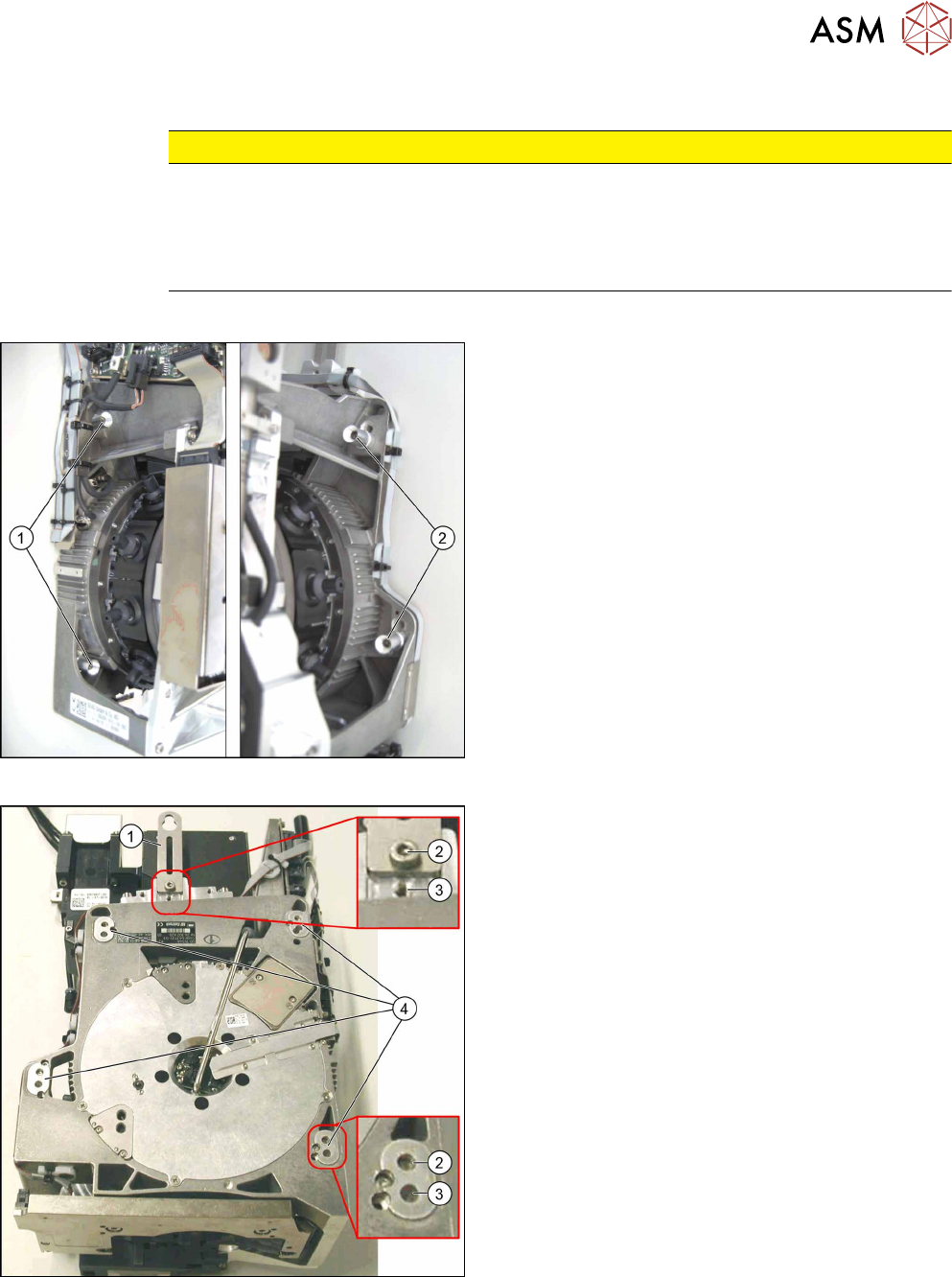
Fig.285: Fastening screws
1. Fastening screws on the left side
2. Fastening screws on the right side
This diagram shows the fastening screws in the "head
at top" position.
Fig.286: CPP head positions
1. Holding bracket
2. "Head at bottom" position
3. "Head at top" position
4. Fixture holes with bushings
8 Placement Heads and Stationary Cameras
8.4 Replacing the SIPLACE TwinHead
210 Service Manual SIPLACE TX Series 06/2017
Conversion to another installation height
Fig.287: Conversion
1. Hole for the fastening screw of the bushing in
"head at bottom" position
2. Hole for the fastening screw of the bushing in
"head at top" position
3. Bushing
All four bushings and the holding bracket must either
be fixed in top or bottom position.
Proceed as follows when replacing the bushings:
► Undo the fastening screws of the bushings.
► Insert the bushings in the correct position and re-
tighten them.
► Perform these steps for all four fastening bush-
ings and the holding bracket of the head.
8.4 Replacing the SIPLACE TwinHead
Parts, equipment and tools
●
SIPLACE Twin Pick&Place module THK R2 [03097485-xx]
You also need the following:
●
Torx screwdriver ESD 1.0-5.0 Nm [03078400-xx]
●
Extension/straight TX20 [03073256-xx]
●
Bit holder for TorqueVario screwdriver [03078706-xx]
●
Extension/straight [03043440-xx]
●
Calibration tool version 3 [03010565-xx]
For additional work to the placement head:
●
Head mount [03056231‑xx]
●
Service manual "SIPLACE TH/VHF head" [DE:00197468‑xx] [EN:00197469‑xx]
Overview
The Twin head consists of two identical Twin segments, which are fitted at an angle of 180°.
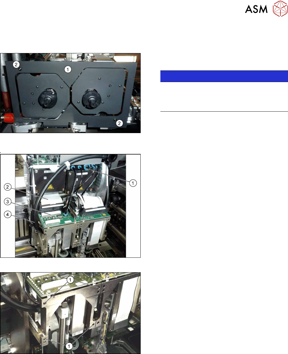
Fig.288: Undetachable screws
NOTICE!
When using modules with undetachable
screws(1) you may need to fit these screws on
the other side depending on the installation posi-
tion.
.
8 Placement Heads and Stationary Cameras
8.4 Replacing the SIPLACE TwinHead
Service Manual SIPLACE TX Series 06/2017 211
Removal
► Switch off the machine, disconnect it from the power supply and secure it to prevent
unauthorized reactivation. Observe the instructions in section 1.2 "Preparatory Work..." [}15].
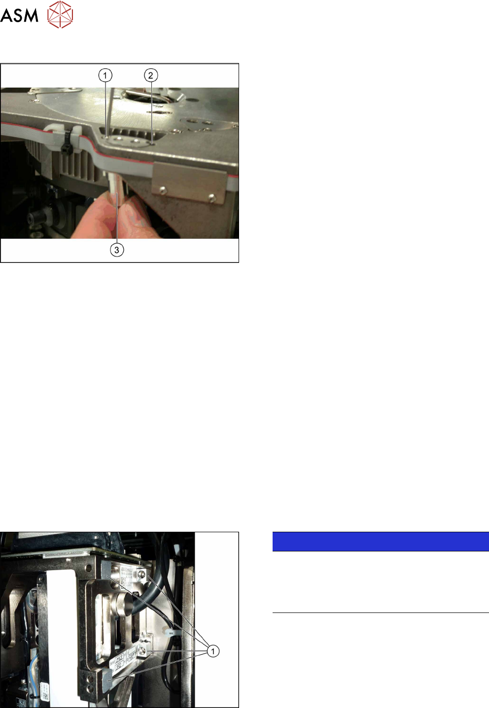
Fig.289: Camera lens hood
► Remove the camera lens hood(1). This is
fastened with two black screws(2).
NOTICE!
Only use these screws to fix the camera lens
hood. This prevents reflection when measuring
components with the stationary camera.
.
Fig.290: Electric and pneumatic connections
► Move the gantry into a position which allows you
best access.
► Unplug the pneumatic connection from the
SIPLACE TwinHead vacuum generator to the
pneumatic distributor(1) and the silencer.
► Disconnect the exhaust air silicone hose from the
TwinHead vacuum generator(4).
► Unplug the pneumatic connection from the pneu-
matic distributor(1) to the SIPLACE TwinHead
return cylinder.
► Unplug the flat ribbon cable(2) from the head
main board(3) on the TwinHead.
Fig.291: Fastening screws
Each module is fixed with four screws to the head
plate and is positioned with two pins.
► Unscrew the first three M4x14 fastening
screws(1) with a long Allen key.
► Hold the module and unscrew the fourth
screw(1).
► Lift the module out of the locating pins.
► Placing the head into the head transport box