00198150-02_SM_TX_en.pdf - 第215页
8 Placement Heads and Stationary Cameras 8.5 Installation Positions on the Head Plate Service Manual SIPLACE TX Series 06/2017 215 8.5.3 Position of Screws on the Attachment Head Suspension Fig.294: Attachment head susp…
8 Placement Heads and Stationary Cameras
8.5 Installation Positions on the Head Plate
214 Service Manual SIPLACE TX Series 06/2017
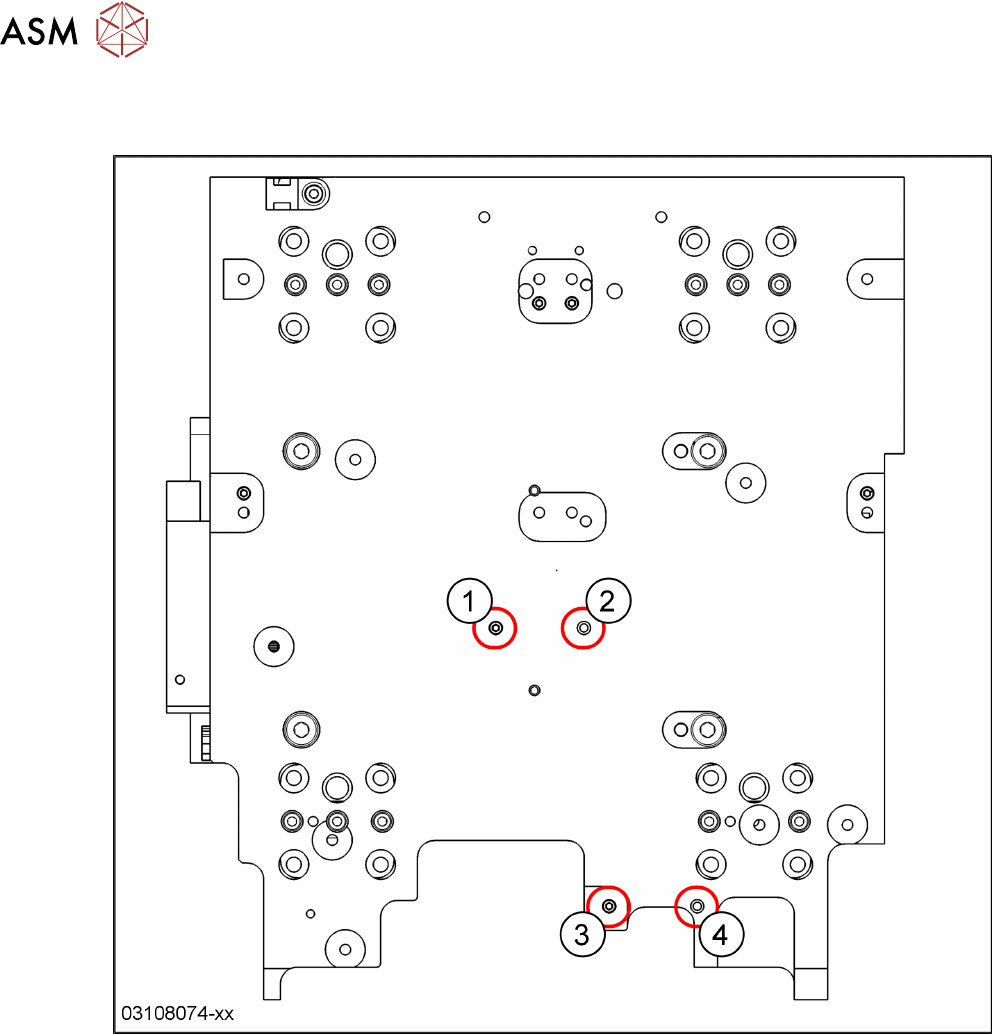
8.5.2 Gantry 2 – Positions of Treaded Pins when Changing from C&P20 P to CPP
and Reverse
Fig.293: Gantry 2: C&P20P head → CPP head
1 C&P20P: threaded pin
CPP: empty
2 C&P20P: empty
CPP: threaded pin
3 C&P20P: threaded pin
CPP: empty
4 C&P20P: empty
CPP: threaded pin
8 Placement Heads and Stationary Cameras
8.5 Installation Positions on the Head Plate
Service Manual SIPLACE TX Series 06/2017 215
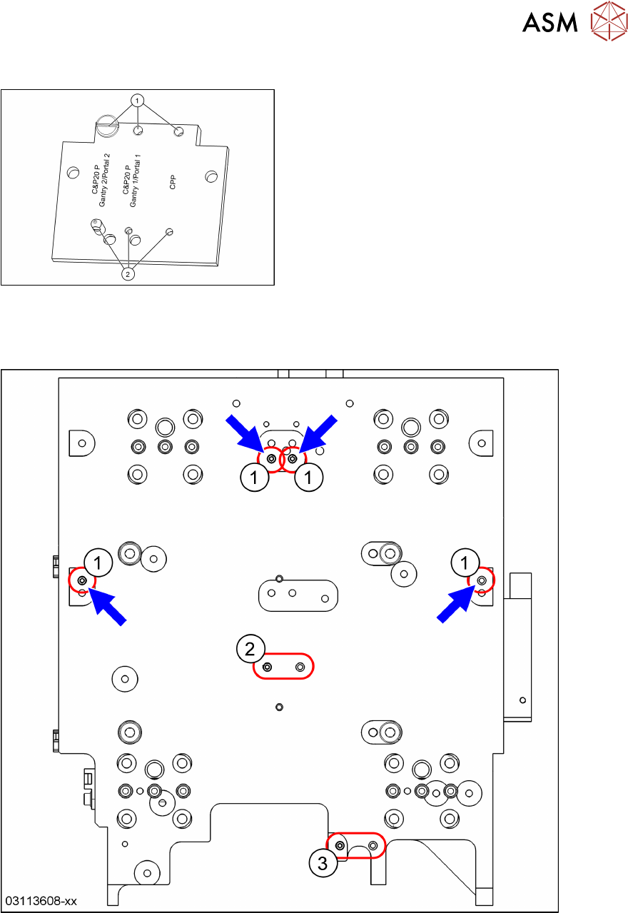
8.5.3 Position of Screws on the Attachment Head Suspension
Fig.294: Attachment head suspension (shown ex-
ample of C&P20P on Gantry 2)
► Set the position of the screw(1) and the
threaded pin(2) according to the placement
head.
► Remove the complete attachment head suspen-
sion when installing a TwinHead.
► The CPP position is the same for Gantry 1
and2.
See also 6.2.9 "Replacing Attachment Head Suspen-
sion [03124850-xx]" [}93].
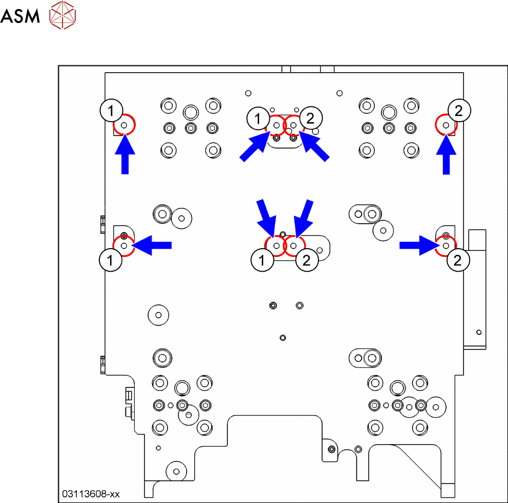
8.5.4 Gantry 1 – Preparing for a TwinHead
Fig.295: Gantry 1: Twin head
1 Threaded pins for TwinHead: Install these pins if not present.
2 Threaded pin from C&P20P or CPP 3 Remove the threaded pin from C&P20P
or CPP.
► Remove the attachment head suspension (see above).
► Check if the two threaded pins(1) are present.
► Remove the threaded pin(3).
8 Placement Heads and Stationary Cameras
8.5 Installation Positions on the Head Plate
216 Service Manual SIPLACE TX Series 06/2017
8.5.5 Gantry 1 – Fixing Points for TwinHead
Fig.296: Gantry 1: Twin head
1 Fixing points left twin module 2 Fixing points right twin module