00198150-02_SM_TX_en.pdf - 第229页
9 Nozzle Changers and Nozzle Stations 9.3 Replacing Nozzle Station [03090348-xx] Service Manual SIPLACE TX Series 06/2017 229 CAUTION Crash hazard! Do not place too many adjusting plates underneath. ► Calibrate the posit…
9 Nozzle Changers and Nozzle Stations
9.2 Replacing the Nozzle Changer
228 Service Manual SIPLACE TX Series 06/2017
9.2.1 Setting the Nozzle Changer Height
Parts, Equipment and Tools
●
Measuring scale
●
NC shim plate (0.3mm) [03021079-xx]
Overview
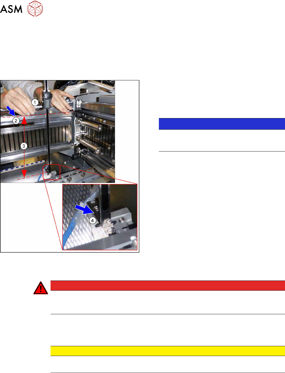
Fig.307: Overview of Measurement Procedure
1. Measuring scale
2. Top edge of the X axis upper linear guide
3. Values to be set (277 +/- 0.2 mm)
4. Nozzle changer contact surface
NOTICE!
Alternatively, you can measure from the top
edge of the lower guide rail of the gantry. In this
case the distance is 116.0+/‑0.2mm.
.
Setting
DANGER
Strong permanent magnet fields
Observe the safety instructions in section 1.1.2 "Safety Instructions for Working with Strong
Magnetic Fields" [}10].
► Remove the nozzle changer (see 9.2 "Replacing the Nozzle Changer" [}227]).
► During the following inside measurement make sure that the tip of the measuring scale does
not tough the magnetic strip as this might scratch it!
CAUTION
Strong magnetic forces
Place a suitable plastic plate between the magnet and measuring scale, if required.
► Position the measuring scale(1) on the top edge of the X axis upper linear guide(2) and
measure the distance to the nozzle changer contact surface(4).
► Hold the measuring scale vertically.
► The setting value (3) is 277+/‑0.2mm.
You can adjust the height, where necessary, by removing or adding NC adjusting plates.
9 Nozzle Changers and Nozzle Stations
9.3 Replacing Nozzle Station [03090348-xx]
Service Manual SIPLACE TX Series 06/2017 229
CAUTION
Crash hazard!
Do not place too many adjusting plates underneath.
► Calibrate the position of the nozzle changer.
9.3 Replacing Nozzle Station [03090348-xx]
Parts, equipment and tools
●
Nozzle station CPx complete / X4iS, XS [03090348-xx]
●
Measuring scale
●
Adjusting plates: support for nozzle reject device [03039514-xx]
Overview
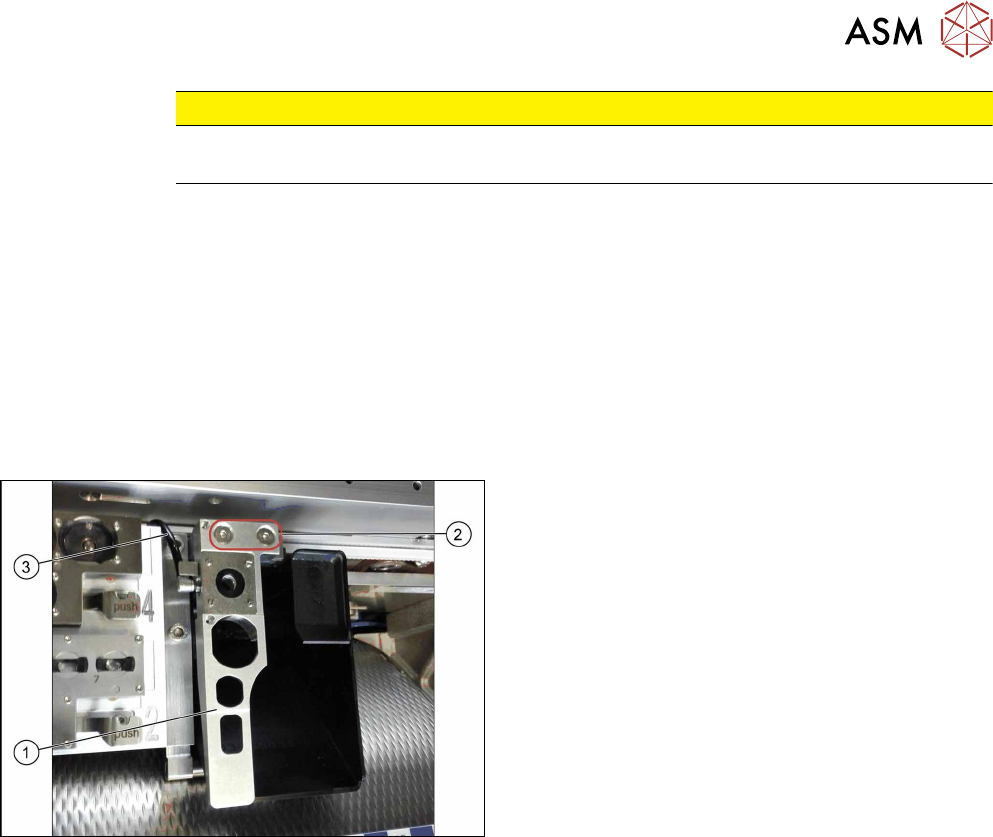
Fig.308: Nozzle station
1. Nozzle station
2. Screws fastening the nozzle station
3. Hose
Removal
► Switch off the machine, disconnect it from the power supply and secure it to prevent
unauthorized reactivation. Observe the instructions in section 1.2 "Preparatory Work..." [}15].
► Remove the two screws(2) fastening the nozzle station(1).
► Unplug the hose(3) for nozzle cleaning.
► Remove the nozzle station.
9 Nozzle Changers and Nozzle Stations
9.3 Replacing Nozzle Station [03090348-xx]
230 Service Manual SIPLACE TX Series 06/2017
Installation
► Follow the removal instructions in reverse order for installation. Also observe the following in-
structions:
CAUTION
Installation instructions
► Check the height of the nozzle station (see below).
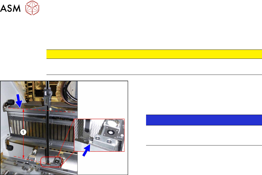
Fig.309: Setting the height of the nozzle station
(taking the standard nozzle station as example)
► The distance(1) between the contact surface of
the nozzle station and the top edge of the upper
guide rail of the gantry needs to be
266.0+0.1/-0.3mm. You may need to use shim
plates to adjust this.
NOTICE!
Alternatively, you can measure from the top
edge of the lower guide rail of the gantry. In this
case the distance is 105.0+0.1/-0.3mm.
.