00198150-02_SM_TX_en.pdf - 第234页
10 COT Insert 10.2 Installation Positions of COT Insert (Table Positions) 234 Service Manual SIPLACE TX Series 06/2017 10.2 Installation Positions of COT Insert (Table Positions) Fig.312: Installation positions The inne…
10 COT Insert
10.1 COT Insert - Overview
Service Manual SIPLACE TX Series 06/2017 233
10 COT Insert
DANGER
Observe User Manual
► Please observe the safety instructions in the user manual for all work!
10.1 COT Insert - Overview
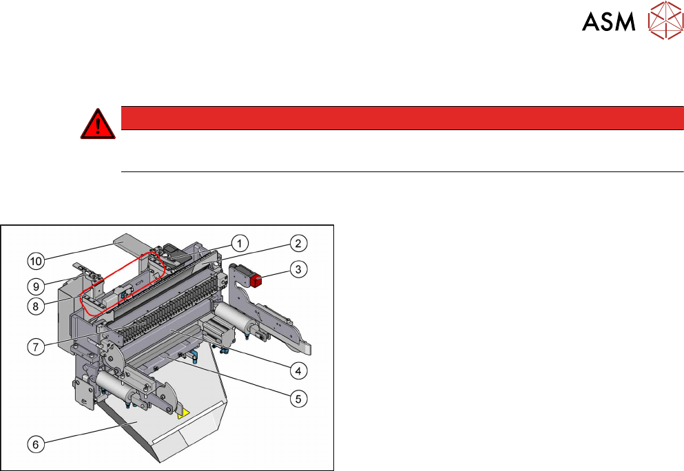
Fig.311: COT insert overview
1. Nozzle station (standard)
2. Empty tape duct
10.6 "Replacing the Empty Tape Duct Assembly
[03052576-xx]" [}244]
3. Safety switch for the component trolley
4. Feeder unlocking device
10.4 "Replacing the 40-Fold Feeder Unlocking
Device [03011582-xx]" [}239]
5. Cutter
6. Waste tape chute
7. Feeder control unit (FCU)
10.5 "Replacing the Feeder Control Unit
(FCU)" [}241]
8. Assembly positions for the nozzle changers
9. Reject bin with nozzle station (optional)
10. Component deposit – reject plate (option)
10.7 "Replacing Component Deposit
[03117664-xx]" [}247]
10 COT Insert
10.2 Installation Positions of COT Insert (Table Positions)
234 Service Manual SIPLACE TX Series 06/2017
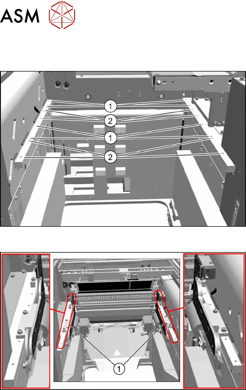
10.2 Installation Positions of COT Insert (Table Positions)
Fig.312: Installation positions
The inner and outer mounting positions depend on the
machine type.
The following installation positions apply to the
SIPLACE TX-Series:
1. COT insert at inner position:
SIPLACE TX1, TX2: location 2
SIPLACE TX2i: location 1 and 2
2. COT insert at outer position:
SIPLACE TX1, TX2: location 1
Fig.313: Example: inner position
Example:
1. COTi central unit mounted at inner position
10 COT Insert
10.3 Replacing the COTi Central Unit and Lifting Mechanics
Service Manual SIPLACE TX Series 06/2017 235
10.3 Replacing the COTi Central Unit and Lifting Mechanics
NOTICE
Working on the COT insert without complete removal of this
For some tasks on the COT insert, it may be enough to just pull the COT insert slightly out
of the machine. In this case, follow the procedure for replacement but observe the following
instructions:
► Remove the screws fastening the central unit and the lifting mechanics.
► You don't usually need to disconnect the cable. However, if the cable is too short, un-
plug it.
► Slightly pull the COT insert out of the machine.
WARNING
Heavy machine parts
► Make sure that the COT insert does not fall out of the machine!
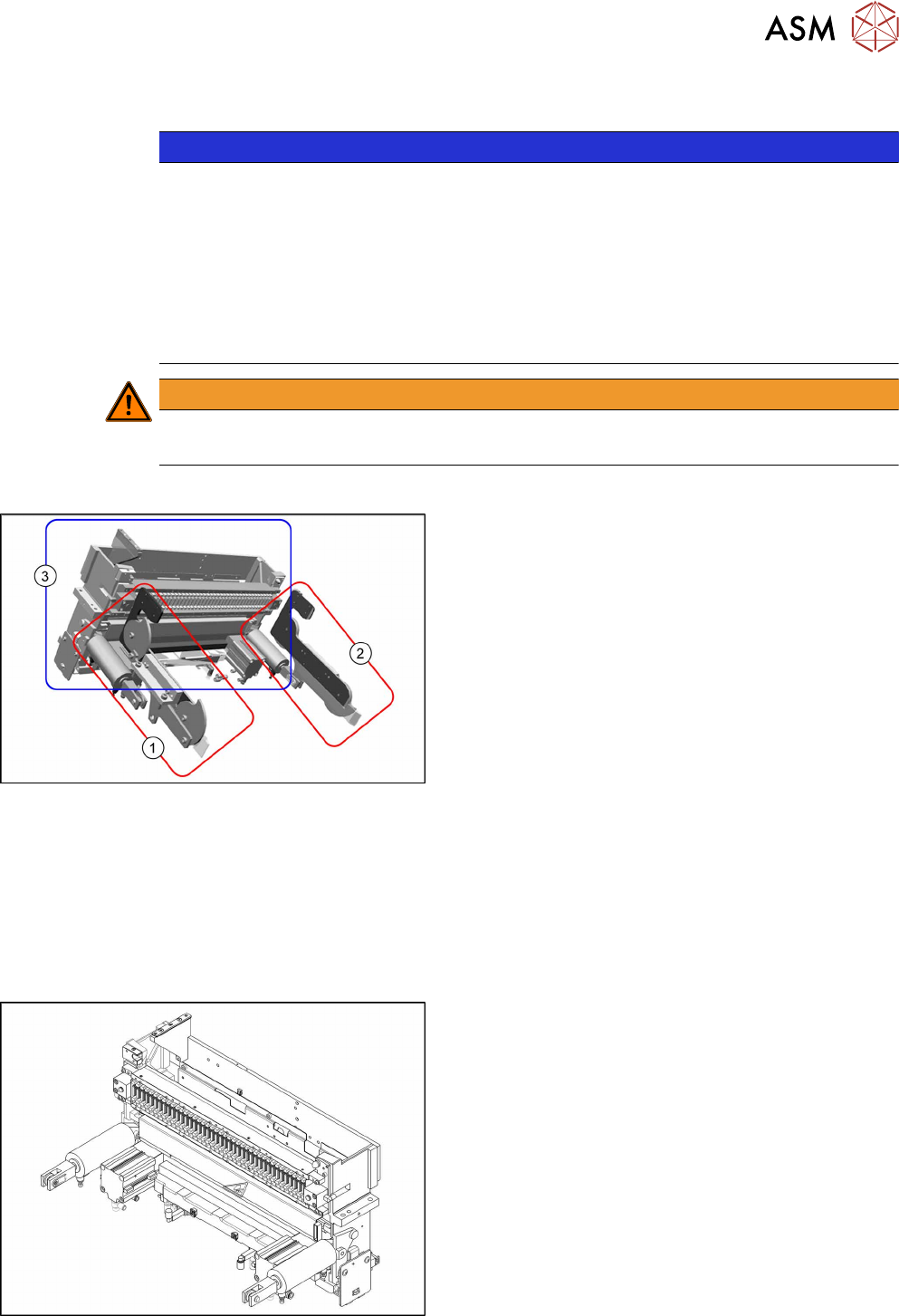
Overview
Fig.314: COTi parts
The COTi for SIPLACE TX machines is split into three
separate parts (units) which are mounted directly to the
machine frame.
These parts are as follows:
1. Lifting mechanics left
2. Lifting mechanics right
3. COTi central unit
The parts are directly fixed with eight screws to the
machine frame (four screws at the COTi central unit and
two screws on each of the lifting mechanics).
For the positions of the COTi in the machine see 10.2 "Installation Positions of COT Insert (Table
Positions)" [}234].
Parts, equipment and tools
●
Suitable lifting device (e.g. hand-operated crane)
●
Detailed circuit diagrams folder for SIPLACE TX-Series (up to no. 499) [DE+EN: 00197933-xx]
●
Detailed circuit diagrams folder for SIPLACE TX-Series (from no. 500) [DE+EN: 00198274-xx]
Fig.315: COTi central unit assembly [03117339‑xx]
(with FCU and tape cutter)
●
Select the required parts (also see below):
– Lifting mechanics left assy [03126040‑xx]
– Lifting mechanics right assy [03126039‑xx]
– COTi central unit assy [03117339‑xx]
(with FCU and tape cutter)