00198150-02_SM_TX_en.pdf - 第237页
10 COT Insert 10.3 Replacing the COTi Central Unit and Lifting Mechanics Service Manual SIPLACE TX Series 06/2017 237 Fig.319: Safety switch ► Repeat for the right lifting mechanics if neces- sary. The procedure for the…
10 COT Insert
10.3 Replacing the COTi Central Unit and Lifting Mechanics
236 Service Manual SIPLACE TX Series 06/2017
Removal of left and right lifting mechanics
NOTICE
Shown by example
The following procedure is shown by example of the left lifting mechanics. The procedure
for the right lifting mechanics the same. Relevant differences will be mentioned.
► Switch off the machine, disconnect it from the power supply and secure it to prevent
unauthorized reactivation. Observe the instructions in section 1.2 "Preparatory Work..." [}15].
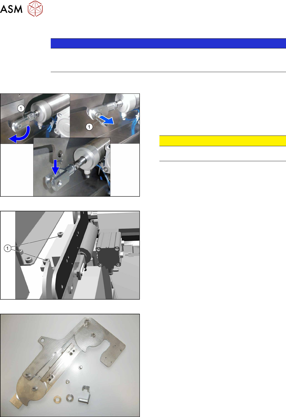
Fig.316: Locking flap
The safety bolt(1) fixes the connection between the
pneumatic cylinder and the lifting mechanics.
► Flip the safety catch down.
► Remove the safety bolt, to access the connec-
tion.
CAUTION!
Pay attention to the position and number of
washers used.
.
Fig.317: Removing the lifting mechanics
► Dismantle the lifting mechanics by removing the
screws(1).
Fig.318: Lifting mechanics parts
► Take out the "left lifting mechanics assem-
bly" [03126040‑xx].
10 COT Insert
10.3 Replacing the COTi Central Unit and Lifting Mechanics
Service Manual SIPLACE TX Series 06/2017 237
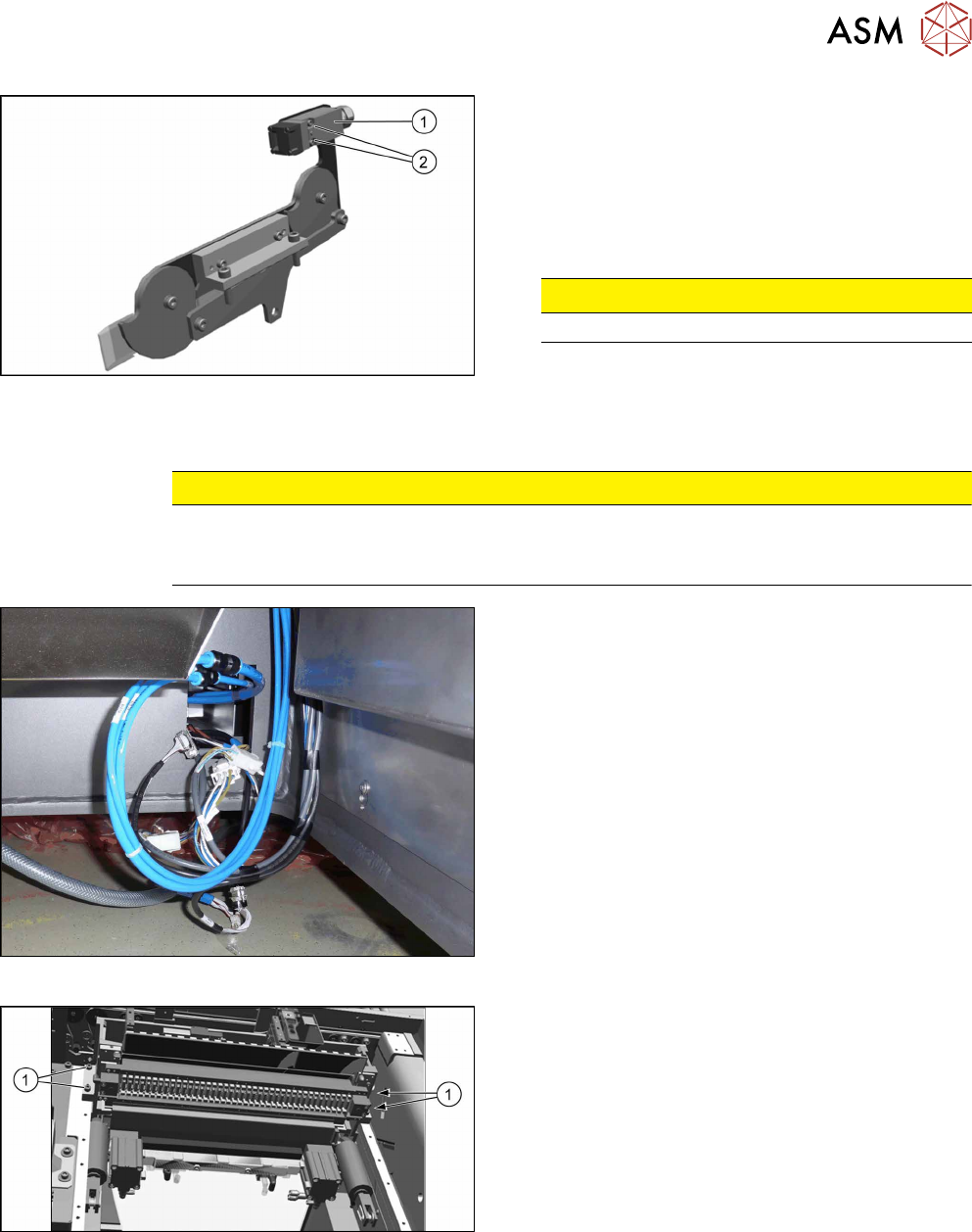
Fig.319: Safety switch
► Repeat for the right lifting mechanics if neces-
sary.
The procedure for the right lifting mechanics is the
same, the only difference being that the safety
switch(1) must be removed.
► Remove the two fastening screws(2) of the
safety switch.
CAUTION!
Do not loose the sleeves.
.
Removing the COTi central unit
CAUTION
Heavy machine part!
The COT central unit is heavy. To lift it out, you will need to use the fit-up aid and a suitable
lifting device (hand-operated crane etc.).
Fig.320: Central unit connections
► Disconnect all connections to the central unit.
Fig.321: Central unit fastening screws
► Remove the four fastening screws(1).
► Remove the central unit out of the machine.
10 COT Insert
10.3 Replacing the COTi Central Unit and Lifting Mechanics
238 Service Manual SIPLACE TX Series 06/2017
Installation of central unit
Follow the removal instructions in reverse order for installation.
► If necessary move the cutter and the FCU from the old to the new COTi.
Replacing the Feeder Control Unit (FCU) [}241]
Replacing the Cutter on the COT Insert [03066690-xx] [}252]
► Lift the COTi into the machine. Use a suitable lifting device.
► Reconnect all cables and hoses. If required, use the detailed circuit diagrams folder.
► Move the COTi into its final position on the machine frame.
Take care not to damage the cables and hoses.
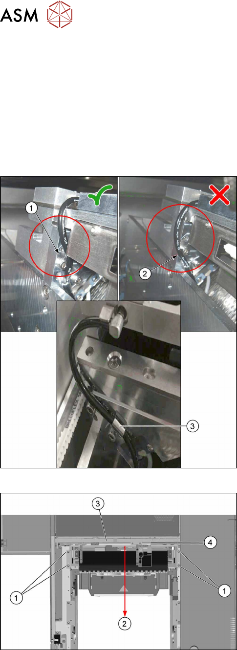
Fig.322: Tubing of the nozzle station air supply
► Check the tubing of the nozzle station air supply:
1. Tubing 1 is recommended. The tube is running
behind the screw head, so the lining of the tube
will not touch the conveyor belt.
2. Tubing 2 is not recommended, as it may touch
the conveyor belt and will be cut over time.
3. Use the hose clamp.
Fig.323: Fixing the central unit (shown from above)
► Put in the four screws(1) in position and loosely
tighten them.
► Move the central unit to the outer side of the
machine(2) to ensure a maximum distance(4) to
the conveyor side(3).
► The further installation of the central unit is performed by following the above instructions in
the reverse order.