00198150-02_SM_TX_en.pdf - 第238页
10 COT Insert 10.3 Replacing the COTi Central Unit and Lifting Mechanics 238 Service Manual SIPLACE TX Series 06/2017 Installation of central unit Follow the removal instructions in reverse order for installation. ► If n…
10 COT Insert
10.3 Replacing the COTi Central Unit and Lifting Mechanics
Service Manual SIPLACE TX Series 06/2017 237
Fig.319: Safety switch
► Repeat for the right lifting mechanics if neces-
sary.
The procedure for the right lifting mechanics is the
same, the only difference being that the safety
switch(1) must be removed.
► Remove the two fastening screws(2) of the
safety switch.
CAUTION!
Do not loose the sleeves.
.
Removing the COTi central unit
CAUTION
Heavy machine part!
The COT central unit is heavy. To lift it out, you will need to use the fit-up aid and a suitable
lifting device (hand-operated crane etc.).
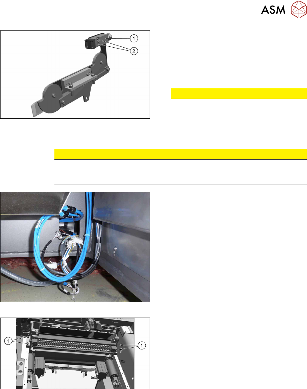
Fig.320: Central unit connections
► Disconnect all connections to the central unit.
Fig.321: Central unit fastening screws
► Remove the four fastening screws(1).
► Remove the central unit out of the machine.
10 COT Insert
10.3 Replacing the COTi Central Unit and Lifting Mechanics
238 Service Manual SIPLACE TX Series 06/2017
Installation of central unit
Follow the removal instructions in reverse order for installation.
► If necessary move the cutter and the FCU from the old to the new COTi.
Replacing the Feeder Control Unit (FCU) [}241]
Replacing the Cutter on the COT Insert [03066690-xx] [}252]
► Lift the COTi into the machine. Use a suitable lifting device.
► Reconnect all cables and hoses. If required, use the detailed circuit diagrams folder.
► Move the COTi into its final position on the machine frame.
Take care not to damage the cables and hoses.
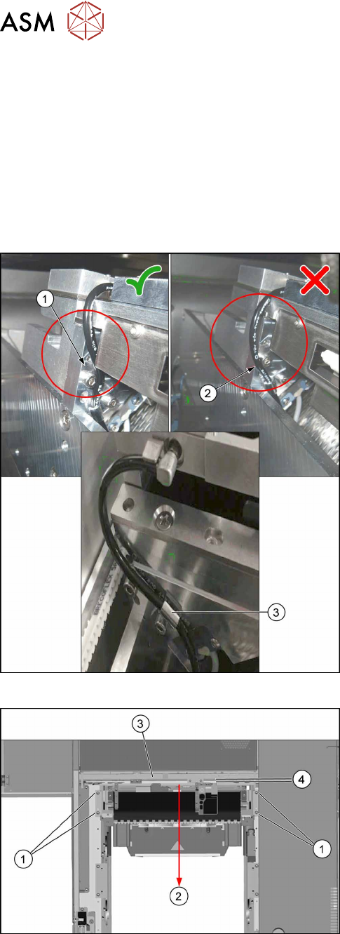
Fig.322: Tubing of the nozzle station air supply
► Check the tubing of the nozzle station air supply:
1. Tubing 1 is recommended. The tube is running
behind the screw head, so the lining of the tube
will not touch the conveyor belt.
2. Tubing 2 is not recommended, as it may touch
the conveyor belt and will be cut over time.
3. Use the hose clamp.
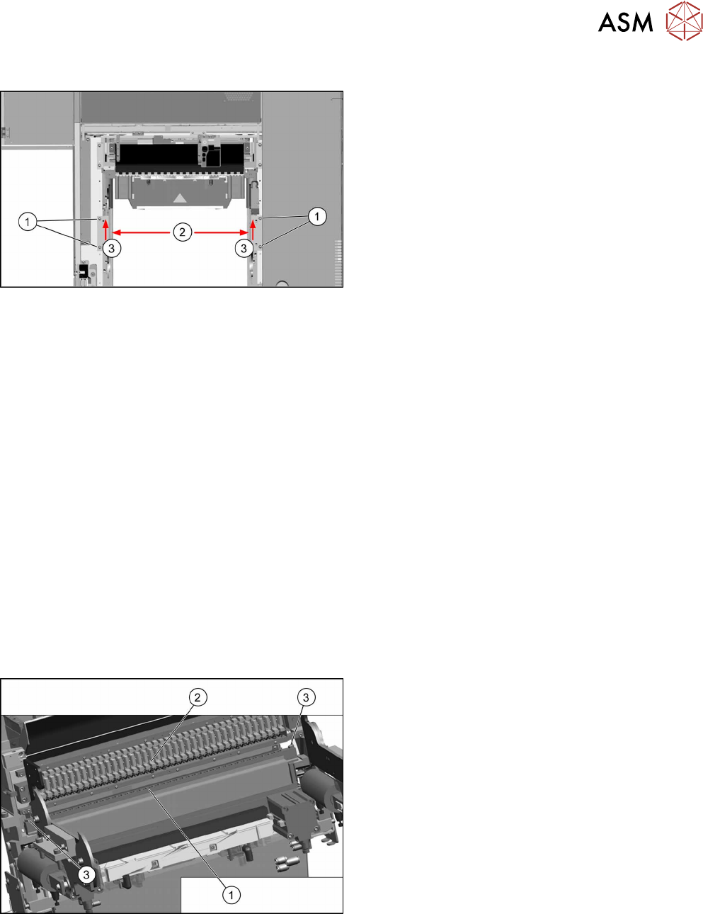
Fig.323: Fixing the central unit (shown from above)
► Put in the four screws(1) in position and loosely
tighten them.
► Move the central unit to the outer side of the
machine(2) to ensure a maximum distance(4) to
the conveyor side(3).
► The further installation of the central unit is performed by following the above instructions in
the reverse order.
10 COT Insert
10.4 Replacing the 40-Fold Feeder Unlocking Device [03011582-xx]
Service Manual SIPLACE TX Series 06/2017 239
Installing the lifting mechanics
Fig.324: Installing the lifting mechanics
► Mount the interlock safety switch to the right lift-
ing mechanics.
► Place both lifting mechanics (left and right) in
position and fix them with two screws(1) each.
► Move both lifting mechanics to the outer posi-
tion(2) push them towards the inner side(3) and
tighten the screws(1).
► Reconnect the lifting mechanics to the pneumatic cylinders.
► Insert the locking flap bolt and place the washers in the correct position! Start at the inner side
at the COTi.
► Close the locking flap to fix the connection between the lifting mechanics and pneumatic cylin-
der.
► Perform necessary calibrations for the location.
See also
2 Replacing the Feeder Control Unit (FCU) [}241]
2 Replacing the Cutter on the COT Insert [03066690-xx] [}252]
10.4 Replacing the 40-Fold Feeder Unlocking Device
[03011582-xx]
Parts, equipment and tools
●
Feeder unlocking device 40-fold [03011582-xx]
Overview
Fig.325: Feeder unlocking device on COTi
1. Feeder unlocking device (under the FCU)
2. Feeder control unit (FCU)
3. Fastening screws (SW10)
The feeder unlocking device is installed at the loca-
tions in the COTi.