00198150-02_SM_TX_en.pdf - 第244页
10 COT Insert 10.6 Replacing the Empty Tape Duct Assembly [03052576-xx] 244 Service Manual SIPLACE TX Series 06/2017 DIP switch S2 [03059783-04] Switch Status Signal Name Description S2.1 ON/OFF FCU_ENV3 ON: test mode fo…
10 COT Insert
10.5 Replacing the Feeder Control Unit (FCU)
Service Manual SIPLACE TX Series 06/2017 243
Installation
► Set the DIP switches on the FCU (see 10.5.1 "Feeder Control Unit (FCU)" [}243]).
► Refit the cover plate and the FCU.
► Place the connection cable in the recess and carefully push in the new FCU. Make sure you
do not pinch any cables.
► Pull the ends of the cables out from under the terminal strip.
► Plug in all electrical connections as labeled on the terminal strip.
► The further installation is performed by following the removal instructions in the reverse order.
10.5.1 Feeder Control Unit (FCU)
●
X-FCU V2, X series [03096377-xx]
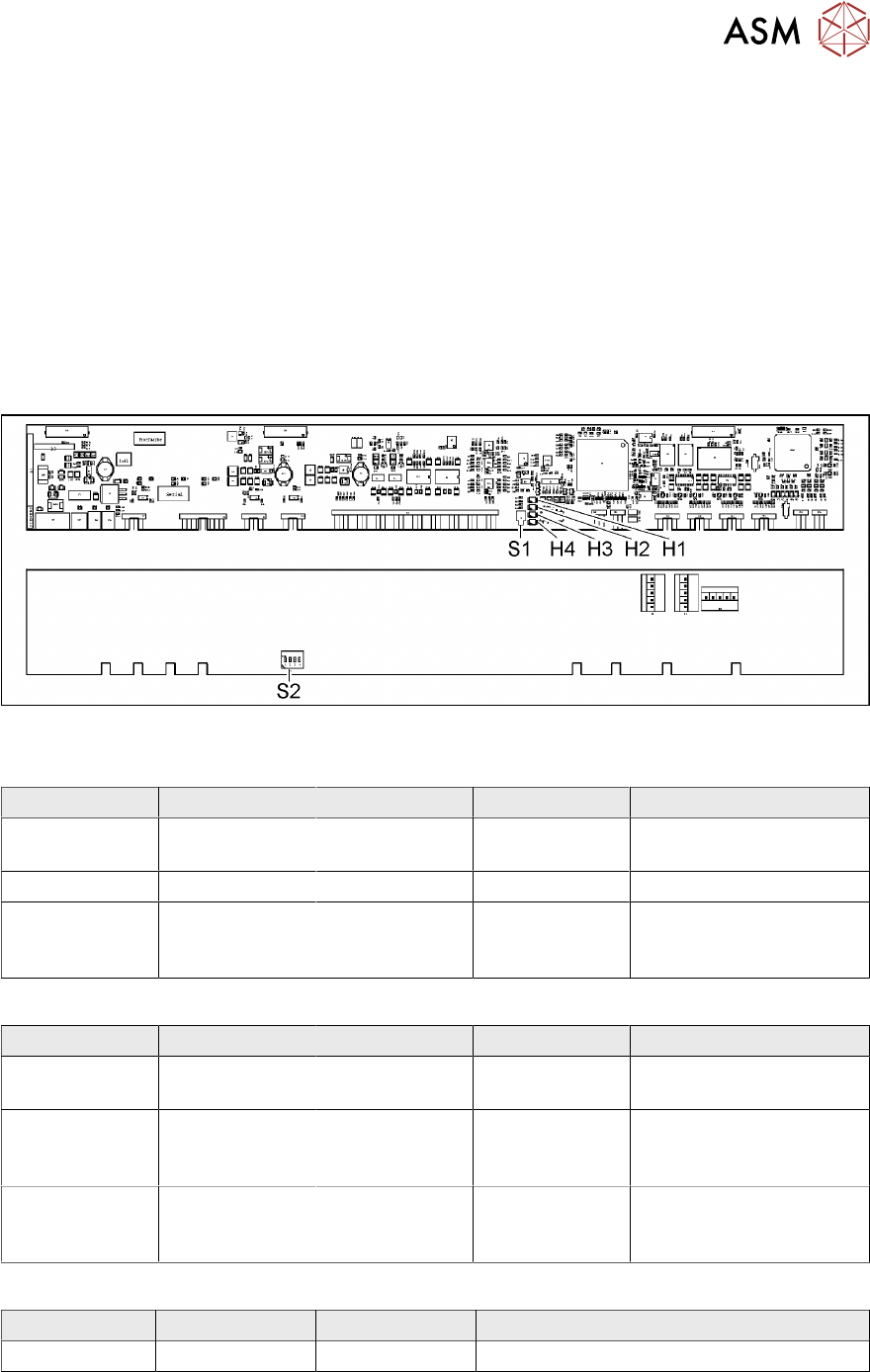
Fig.333: FCU board
LED (test mode for reject box switched off – S2.1 ON) [03059783-04]
LED Color Status Signal Name Description
H1, H2, H3, H4 GN Sequential shift
light
LED1, 2, 3, 4 FCU OK
H1, H2, H3, H4 GN ON LED1, 2, 3, 4 eSW application missing
H1, H2, H3, H4 GN Flashing LED1, 2, 3, 4 FCU error, reboot place-
ment machine or replace
FCU
LED (test mode for reject box switched on – S2.1 OFF) [03059783-04]
LED Color Status Signal Name Description
H1 or H2 or H3
or H4
GN Flashes LED1 or 2 or 3
or 4
No sensor connected for
reject box 1 or 2 or 3 or 4
H1 or H2 or H3
or H4
GN OFF LED1 or 2 or 3
or 4
Sensor for reject boxes 1
or 2 or 3 or 4 connected
and no reject box inserted
H1 or H2 or H3
or H4
GN ON LED1 or 2 or 3
or 4
Sensor for reject boxes 1
or 2 or 3 or 4 connected
and no reject box inserted
Button S1 [03059783-04]
Button Status Function Description
S1 OFF RESET When pressed
10 COT Insert
10.6 Replacing the Empty Tape Duct Assembly [03052576-xx]
244 Service Manual SIPLACE TX Series 06/2017
DIP switch S2 [03059783-04]
Switch Status Signal Name Description
S2.1 ON/OFF FCU_ENV3 ON: test mode for reject box switched off
OFF: test mode for reject box switched on
S2.2 OFF FCU_ENV2 40-fold FCU
S2.3 ON/OFF FCU_ENV1 ON: without insert control, with virtual but-
ton
OFF: with insert control, without virtual but-
ton
S2.4 ON/OFF FCU_ENV0 ON: with tape cutter and with nozzle
changer functionality
OFF: without tape cutter and without nozzle
changer functionality
If an "X-FCU / X-Series" [03059623-xx] is fitted as replacement for an "FCU X-Series" [03020068-
xx] in the "COT insert X-Series" or at the "Docking station for component trolley SIPLACE X", you
need to set the DIP switch as follows:
Switch Status Comment
S2.1 ON Test mode for reject bin switched off
S2.2 OFF FCU for 40 feed tracks
S2.3 OFF COT insert control with pushbutton / without button GUI (vir-
tual).
S2.4 OFF "HW version 6" meaning without tape cutter and nozzle
changer functionality
10.6 Replacing the Empty Tape Duct Assembly [03052576-xx]
Parts, equipment and tools
Select the required spare part:
●
Empty-tape duct assembly standard TX assembly [03121375-xx]
●
Empty-tape duct, short TX assembly [03121376-xx]
Overview
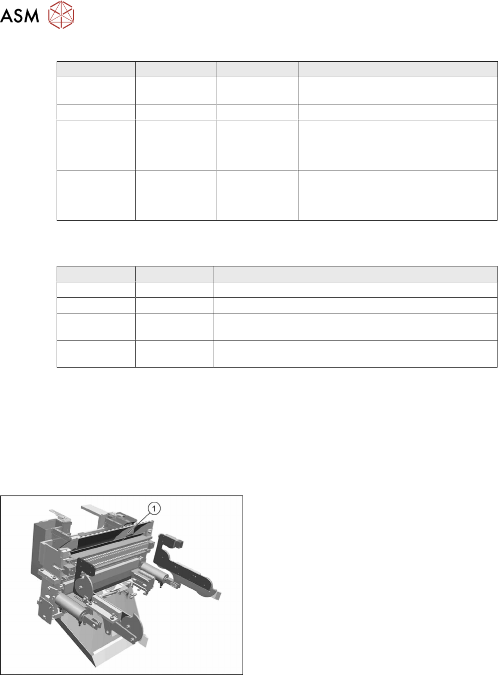
Fig.334: Empty tape duct assembly
1. Empty tape duct assembly
10 COT Insert
10.6 Replacing the Empty Tape Duct Assembly [03052576-xx]
Service Manual SIPLACE TX Series 06/2017 245
CAUTION
Risk of cutting
The cutter is located under the tape channel. The blades have very sharp edges.
► Do not reach into the cutter and make sure that it is never left unmonitored or freely
accessible.
Removal
► Switch off the machine, disconnect it from the power supply and secure it to prevent
unauthorized reactivation. Observe the instructions in section 1.2 "Preparatory Work..." [}15].
► Move out the COTi central unit from the machine about 50mm (see 10.3 "Replacing the COTi
Central Unit and Lifting Mechanics" [}235]).
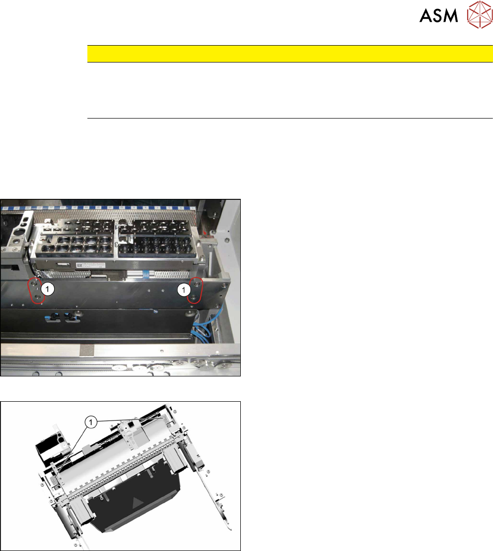
Fig.335: Removing nozzle changer
► Remove the four screws(1) fastening the nozzle
changer carrier to the back of the COTi.
Fig.336: Empty tape duct fastening screws
► Remove the two screws(1) fastening the empty
tape duct assembly.