00198150-02_SM_TX_en.pdf - 第247页
10 COT Insert 10.7 Replacing Component Deposit [03117664-xx] Service Manual SIPLACE TX Series 06/2017 247 10.7 Replacing Component Deposit [03117664-xx] Parts, equipment and tools ● Component deposit assembly [03117664-x…
10 COT Insert
10.6 Replacing the Empty Tape Duct Assembly [03052576-xx]
246 Service Manual SIPLACE TX Series 06/2017
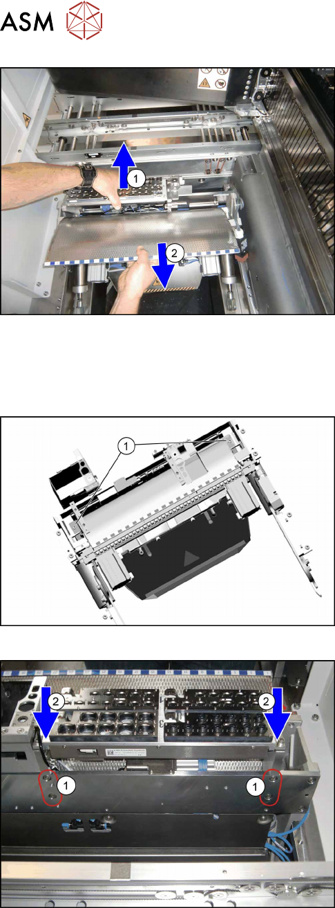
Fig.337: Removing empty tape duct
► Carefully lift the nozzle changer carrier(1) and
the empty tape duct assembly(2)off.
Pay attention to all the wires and cables leading
from the nozzle changer.
Installation
► Follow the removal instructions in reverse order for further installation. Also observe the fol-
lowing instructions:
Fig.338: Fixing empty tape duct
► Fix the new empty tape duct assembly with two
screws(1).
Fig.339: Refitting the nozzle changer
► Fasten the nozzle changer carrier from the back.
Press the nozzle changer carrier downwards(2),
while you tighten the four screws(1).
► Reassemble the complete COT central unit (see 10.3 "Replacing the COTi Central Unit and
Lifting Mechanics" [}235]).
► Check the nozzle changer height (see 9.2.1 "Setting the Nozzle Changer Height" [}228]) and
recalibrate the nozzle changer.
► Perform necessary calibrations for the location.
10 COT Insert
10.7 Replacing Component Deposit [03117664-xx]
Service Manual SIPLACE TX Series 06/2017 247
10.7 Replacing Component Deposit [03117664-xx]
Parts, equipment and tools
●
Component deposit assembly [03117664-xx]
Overview
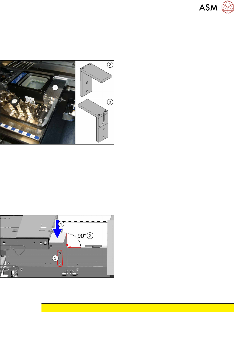
Fig.340: Component deposit on COTi
The component deposit is an option.
1. Component deposit, fitted
2. Component deposit front view
3. Component deposit back view
Removal
► Switch off the machine, disconnect it from the power supply and secure it to prevent
unauthorized reactivation. Observe the instructions in section 1.2 "Preparatory Work..." [}15].
► Locations with a JTF: You may want to move out the COTi central unit from the machine
about 50 mm for better access (see 10.3 "Replacing the COTi Central Unit and Lifting Mech-
anics" [}235]).
► Unscrew the component deposit from the backside.
Installation
Fig.341: Mounting the component deposit
► Fit the new component deposit:
Press it down(1), align it 90° to the COTi central
unit(2) and tighten the two screws(3).
► Follow the removal instructions in reverse order for further installation. Also observe the fol-
lowing instructions:
CAUTION
Installation instructions
► Reassemble the COTi central unit (see 10.3 "Replacing the COTi Central Unit and Lift-
ing Mechanics" [}235]).
► Perform necessary calibrations for the location.

10 COT Insert
10.7 Replacing Component Deposit [03117664-xx]
248 Service Manual SIPLACE TX Series 06/2017