00198150-02_SM_TX_en.pdf - 第251页
11 Cutter 11.2 Replacing the Waste Tape Chute [03125182-xx] Service Manual SIPLACE TX Series 06/2017 251 11.2 Replacing the Waste Tape Chute [03125182-xx] Parts, equipment and tools ● Waste chute welding assembly [031251…
11 Cutter
11.1 Cutter overview
250 Service Manual SIPLACE TX Series 06/2017
11.1 Cutter overview
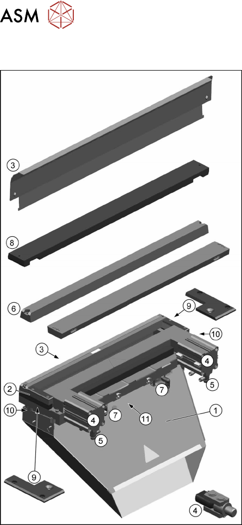
Fig.342: Cutter parts
1. Waste tape chute
11.2 "Replacing the Waste Tape Chute
[03125182-xx]" [}251]
2. Cutter
11.3 "Replacing the Cutter on the COT Insert
[03066690-xx]" [}252]
3. Baffle plate
11.5 "Replacing the Baffle Plate [03019896-
xx]" [}257]
4. Short-stroke cylinder with articulated joint
11.8 "Replacing the Short-Stroke Cylinder
[03038587-xx]" [}262]
11.7 "Replacing the Articulated Joint on the
Short-Stroke Cylinder [03000518-xx]" [}259]
5. Throttle valve
11.13 "Replacing the Throttle Valve [03000600-
xx]" [}274]
6. Cutter blades
11.9 "Replacing the Cutter Blades" [}264]
7. Solenoid valves and silencer
11.14 "Replacing the Solenoid Valves [03000630-
xx]" [}276]
11.15 "Replacing the Silencer [00310744-
xx]" [}277]
8. Wiper
11.10 "Replacing Wiper [03000491-xx]" [}270]
9. Wiper clips
11.11 "Replacing Wiper Clip" [}271]
10. Metal buffer and spacer distance piece
11.4 "Replacing the Metal Buffer/Spacer Distance
Piece" [}255]
11.12 "Replacing the Cutter Cable
[03063590‑xx]" [}273]
11 Cutter
11.2 Replacing the Waste Tape Chute [03125182-xx]
Service Manual SIPLACE TX Series 06/2017 251
11.2 Replacing the Waste Tape Chute [03125182-xx]
Parts, equipment and tools
●
Waste chute welding assembly [03125182‑xx]
Removal
CAUTION
Risk of cutting
The cutter is located under the tape channel. The blades there have very sharp edges.
► Do not reach into the tape cutter.
► Make sure that the cutter is not freely accessible to unauthorized persons.
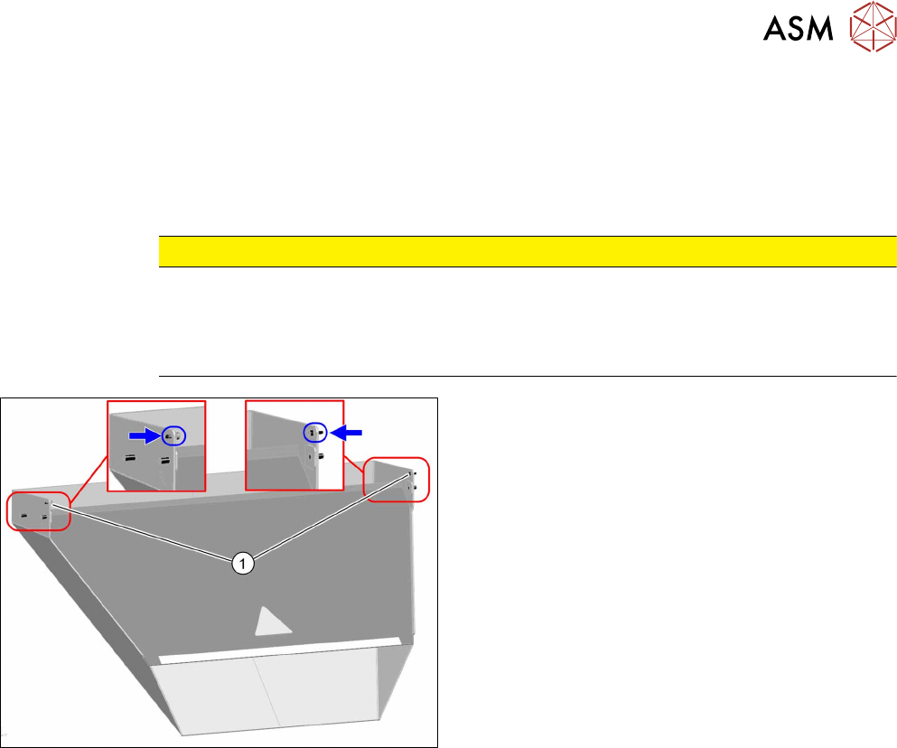
Fig.343: Waste tape chute
► Loosen the two safety screws(1) on the waste
tape chute and unhook the waste tape chute.
Installation
► Follow the removal instructions in reverse order for installation.
11 Cutter
11.3 Replacing the Cutter on the COT Insert [03066690-xx]
252 Service Manual SIPLACE TX Series 06/2017
11.3 Replacing the Cutter on the COT Insert [03066690-xx]
Parts, equipment and tools
●
Cutter, pneumatic SIPLACE HF/X-Series [03066690-xx]
●
If needed, mounting plate [00312731-xx]
Alternatively: two large parallel clamps and a sturdy table with even surface to clamp down
the dismantled cutter
Overview
Fig.344: Cutter overview
1. Cutter
2. Short-stroke cylinder
3. Support plate on cutter
4. Electrical connections
5. Main air supply
6. Waste tape chute
Removal
NOTICE
COT insert
The cutter can be removed without dismantling the COT insert.
► Switch off the machine, disconnect it from the power supply and secure it to prevent
unauthorized reactivation. Observe the instructions in section 1.2 "Preparatory Work..." [}15].
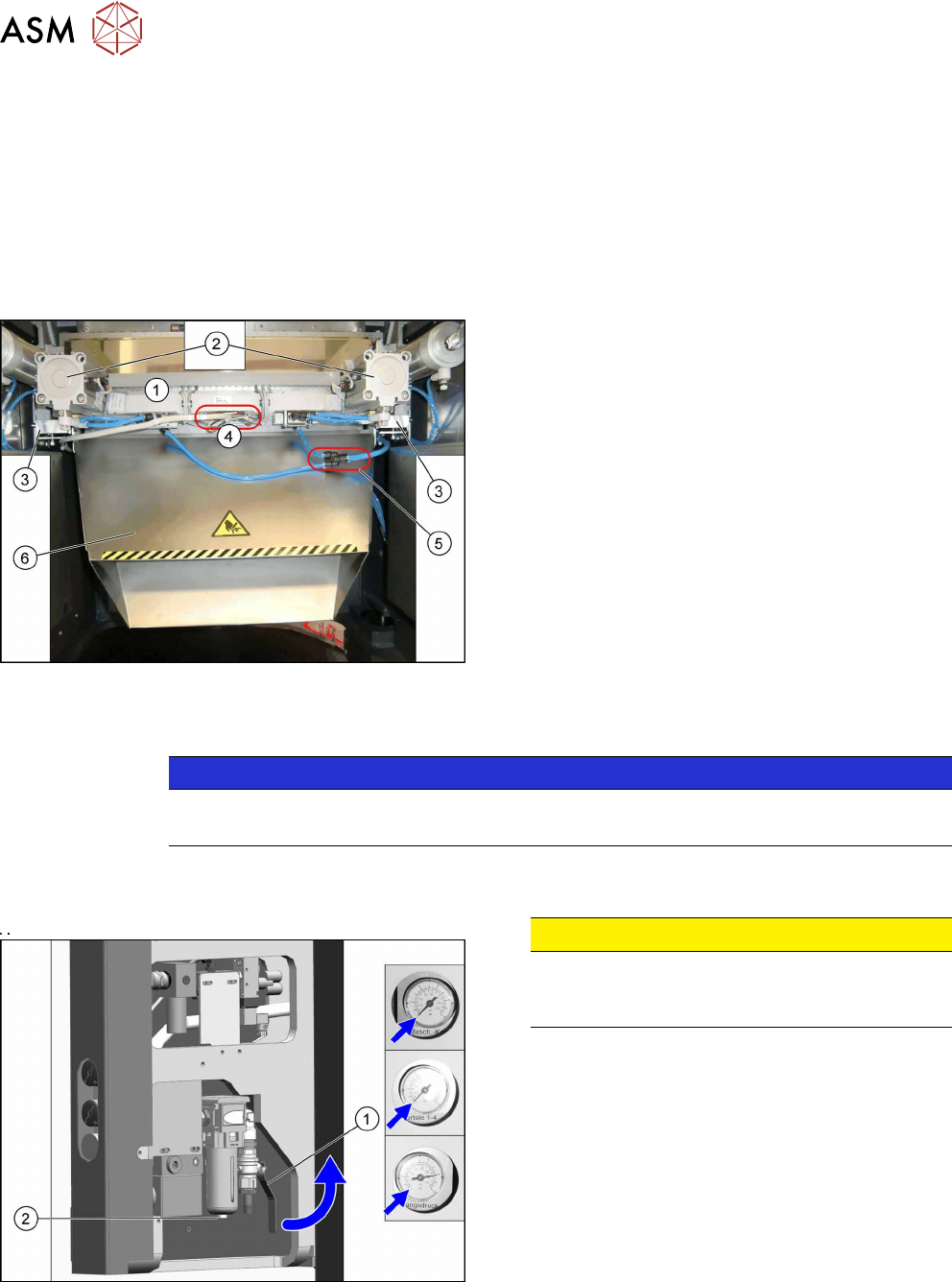
Fig.345: Disabling the compressed air supply
CAUTION!
Switch off the compressed air supply.
When working on the pneumatic system, always
switch off the compressed air supply.
.
► Push the lever (1) for the compressed air supply
back, until it is positioned horizontally.
► Open the screw (2) on the inlet filter to vent the
system. Hold a cloth underneath to capture any
escaping oil.
► All pressure gauges must be set to zero.
► Remove the waste tape chute (see 11.2 "Replacing the Waste Tape Chute
[03125182-xx]" [}251]).
► Unplug all electrical connections and cut all cable ties along this cable.
► Unplug the main air supply and cut all cable ties along this tubing.