00198150-02_SM_TX_en.pdf - 第254页
11 Cutter 11.3 Replacing the Cutter on the COT Insert [03066690-xx] 254 Service Manual SIPLACE TX Series 06/2017 Fig.350: Pulling out the cutter ► Slide out the cutter unit on the support edge of the machine. CAUTION Ad…
11 Cutter
11.3 Replacing the Cutter on the COT Insert [03066690-xx]
Service Manual SIPLACE TX Series 06/2017 253
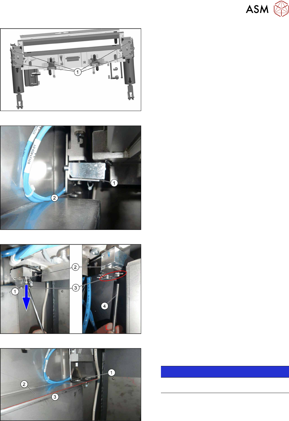
Fig.346: Cutter fastening screws
► Remove the four fastening screws(1) on the cut-
ter mount.
Fig.347: Cutter on lifting aid
► The cutter mount(1) will move downwards to the
support plate(2).
Fig.348: Moving the cutter down
► Loosen the screw on the cutter lifting aid(1).
► Move the entire lifting aid downwards(2) until it
touches the end position(3).
► Remove the long screw(4).
Fig.349: Lifting aid and support edge
The cutter lifting aid(1) is level(3) with the support
edge of the sliding plate(2).
NOTICE!
For better view the picture is without cutter. The
cutter will be removed in the following step.
.
11 Cutter
11.3 Replacing the Cutter on the COT Insert [03066690-xx]
254 Service Manual SIPLACE TX Series 06/2017
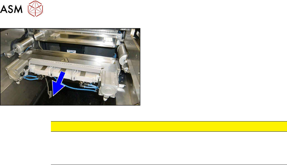
Fig.350: Pulling out the cutter
► Slide out the cutter unit on the support edge of
the machine.
CAUTION
Additional work
► For all further work, either fix the cutter to the mounting plate with four hexagon
socket-head screws M6 or use screw clamps to fasten the cutter to a sturdy table.
► Do not place the cutter onto the pneumatic connections (down on the lifting cylinders).
Installation
► Installation is performed by following the above instructions in reverse order.
11 Cutter
11.4 Replacing the Metal Buffer/Spacer Distance Piece
Service Manual SIPLACE TX Series 06/2017 255
11.4 Replacing the Metal Buffer/Spacer Distance Piece
Parts, equipment and tools
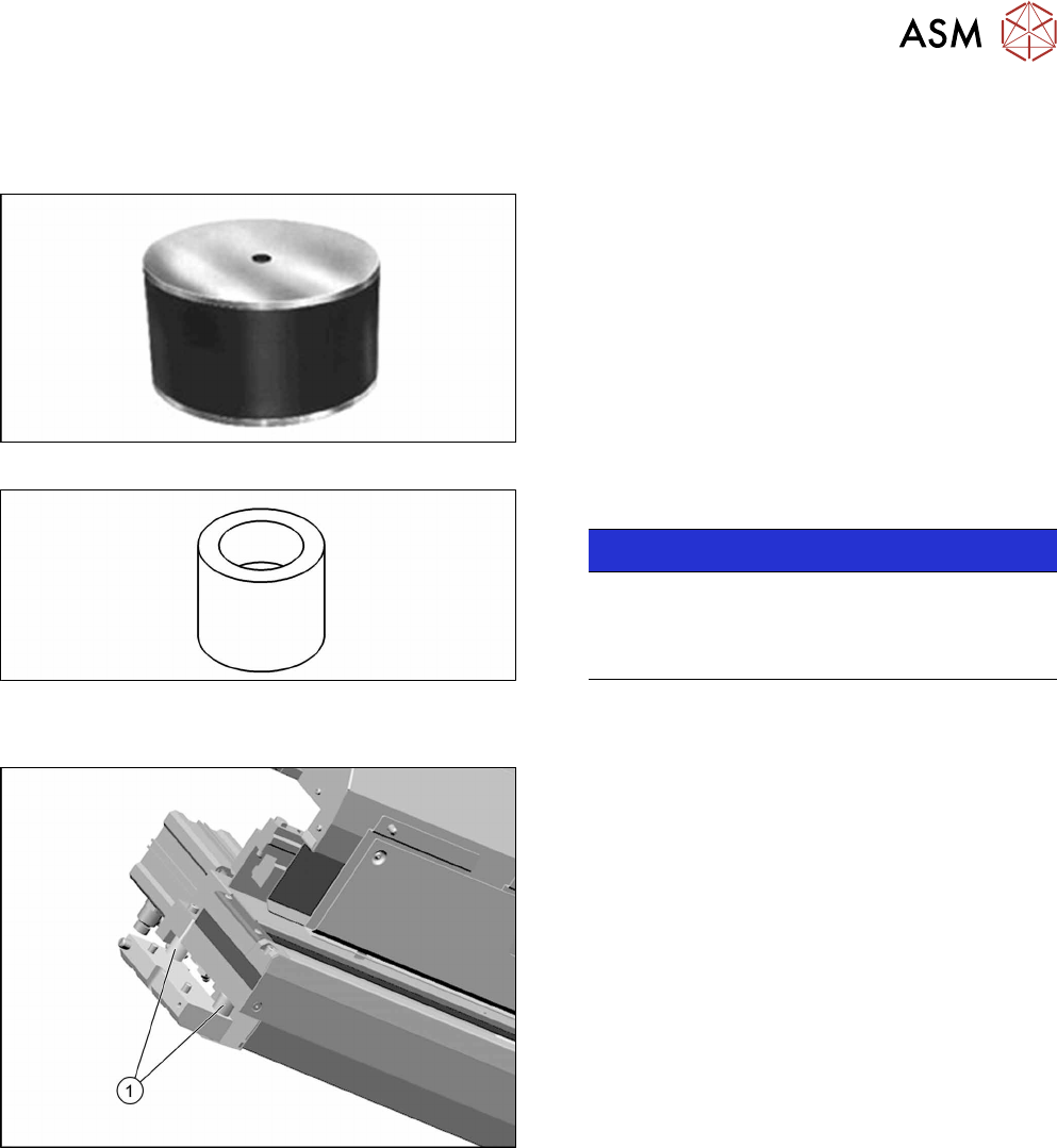
Fig.351: Metal buffer
●
Metal buffer M4.65 Shore [00329209-xx]
Fig.352: Spacer distance piece
●
Spacer distance piece [03007432-xx]
NOTICE!
Same procedure
The removal and installation of the spacer dis-
tance piece is the same as that for the metal buf-
fer. The metal buffer is described below.
.
Overview
Fig.353: Metal buffer and spacer distance piece on cutter
1. Metal buffer and spacer distance piece (2 on
each side)
The metal butters absorb the cutting vibration to
the machine frame.