00198150-02_SM_TX_en.pdf - 第262页
11 Cutter 11.8 Replacing the Short-Stroke Cylinder [03038587-xx] 262 Service Manual SIPLACE TX Series 06/2017 11.8 Replacing the Short-Stroke Cylinder [03038587-xx] Parts, equipment and tools ● Short-stroke cylinder 50x4…
11 Cutter
11.7 Replacing the Articulated Joint on the Short-Stroke Cylinder [03000518-xx]
Service Manual SIPLACE TX Series 06/2017 261
Installation
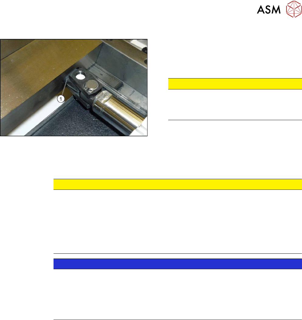
Fig.363: Installing the articulated joint
► Screw the articulated joint into the short-stroke
cylinder with a torque of 22Nm. Make sure that
the joint (1) is horizontal so that it fits into the re-
cess in the moveable blade. Secure the screw
with Loctite243.
CAUTION!
The articulated joint must be horizontal. If not,
the blades could be distorted, which will then
cause the joint to break.
.
► Screw the articulated joint to the moveable blades. Tighten the screws to a torque of 6 Ncm.
► Follow the removal instructions in reverse order for further installation. Also observe the fol-
lowing instructions:
CAUTION
Installation instructions
► Grease the articulated joints slightly with "Klüber BEM 34-132 lubricant grease".
► Secure the screws with Loctite 243.
► Insert the new screw caps. Remove the protruding plastic residues with a knife.
► Connect the compressed air hoses to the cylinder in the correct allocation.
► Check the gap between the leading edge of the tape deflector and the "empty-tape
baffle, inside".
NOTICE
If the tapes are not cut correctly.
If the tapes are not cut correctly, even though the switching points have been set properly
and the short-stroke cylinder has been exchanged - complete with the one-way restrictor -
the cause of the problem may be:
► Incorrect compressed air level
► Leaking compressed air connection or Y-socket union
See also
2 Replacing the Cutter on the COT Insert [03066690-xx] [}252]
11 Cutter
11.8 Replacing the Short-Stroke Cylinder [03038587-xx]
262 Service Manual SIPLACE TX Series 06/2017
11.8 Replacing the Short-Stroke Cylinder [03038587-xx]
Parts, equipment and tools
●
Short-stroke cylinder 50x40 ECDQ2B50-0040-CEJ00119 [03038587-xx]
●
Loctite 243 [00334892‑xx]
Removal
► Switch off the machine, disconnect it from the power supply and secure it to prevent
unauthorized reactivation. Observe the instructions in section 1.2 "Preparatory Work..." [}15].
► Remove the cutter from the machine.
Replacing the Cutter on the COT Insert [03066690-xx] [}252]
► Remove the articulated joint from the short-stroke cylinder (5).
Replacing the Articulated Joint on the Short-Stroke Cylinder [03000518-xx] [}259]
1
6
5
4
3
2
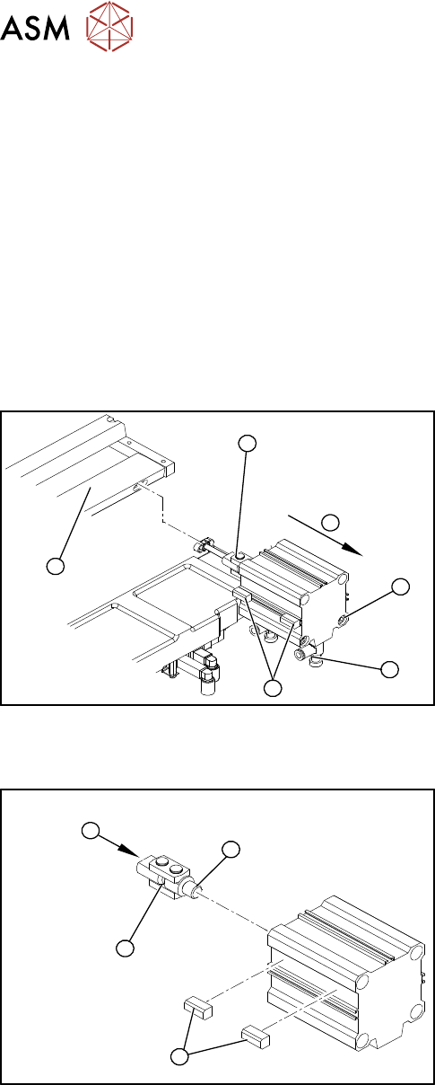
Fig.364: Removing the short-stroke cylinder
► Use a permanent marker to mark the exact in-
stallation position of the proximity switch (1) on
the short-stroke cylinder.
► Remove the screws fastening the two inductive
proximity switches (1) to the short-stroke cylinder.
► Remove the compressed air connections (2) on
the short-stroke cylinder. You may want to mark
their positions to make clear assignment easier
later on.
► Remove the two screws (3) fastening the short-
stroke cylinder.
► Remove the short-stroke cylinder (4) from the
cutter.
Installation
1
4
3
2
Fig.365: Fitting the articulated joint and proximity switches
► Apply a small amount of Loctite243 to the thread
(2) of the new articulated joint.
► Screw the articulated joint (1) into the short-
stroke cylinder.
► Turn the articulated joint in its installation posi-
tion(3).
Once the cylinder is installed, the slot in the
moveable blade prevents the articulated joint
from turning.
► Copy the exact installation position of the proxim-
ity switch(4) onto the new short-stroke cylinder
(e.g. with a feeler gauge, fine-tipped marker pen).
11 Cutter
11.8 Replacing the Short-Stroke Cylinder [03038587-xx]
Service Manual SIPLACE TX Series 06/2017 263
1
3
2
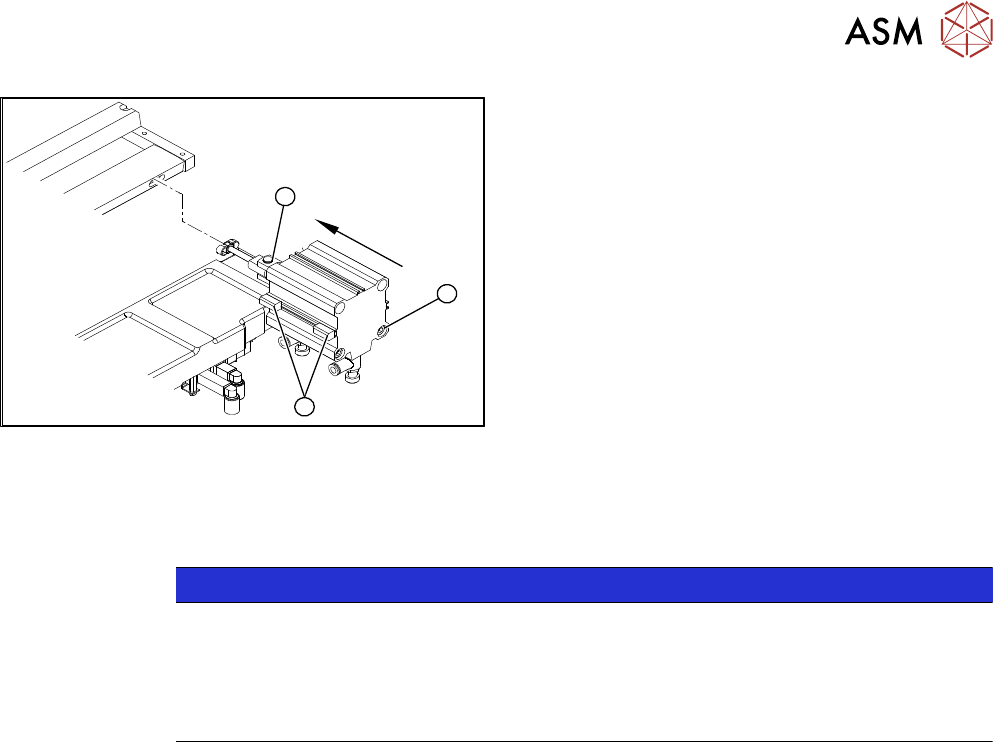
Fig.366: Fitting the short-stroke cylinder
► Fit the proximity switch (1) precisely in the posi-
tion you marked with the permanent marker.
► Place the prepared cylinder into the cutter, in the
correct rotary position of the articulated joint (2).
► Fasten the cylinder in this position, with the two
screws provided(3) (Loctite243).
► Connect the compressed air hoses to the cylinder in the correct allocation.
► Further installation is performed by following the above instructions in the reverse order. Ob-
serve the following instructions:
NOTICE
Installation instructions
► Also observe section 11.7 "Replacing the Articulated Joint on the Short-Stroke Cylin-
der [03000518-xx]" [}259].
► From SW707.1: set the restrictors (see 11.13.1 "Times for Setting the Throttle on the
Cutter (From SW707.1)" [}275]).
See also
2 Times for Setting the Throttle on the Cutter (From SW707.1) [}275]
2 Replacing the Articulated Joint on the Short-Stroke Cylinder [03000518-xx] [}259]
2 Replacing the Cutter on the COT Insert [03066690-xx] [}252]