00198150-02_SM_TX_en.pdf - 第272页
11 Cutter 11.11 Replacing Wiper Clip 272 Service Manual SIPLACE TX Series 06/2017 Removal ► Switch off the machine, disconnect it from the power supply and secure it to prevent unauthorized reactivation. Observe the inst…
11 Cutter
11.11 Replacing Wiper Clip
Service Manual SIPLACE TX Series 06/2017 271
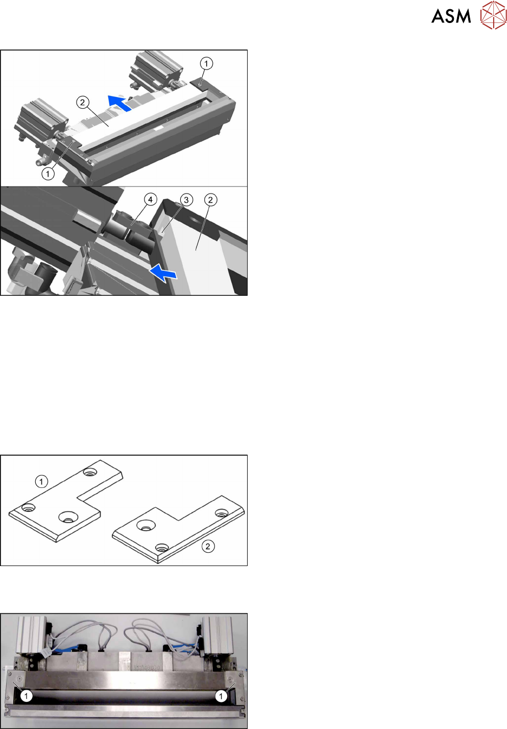
Fig.380: Removing the wiper
► Remove the two screws(1) fixing the wiper(2).
► Remove the wiper(2).
The notch(3) in the wiper will move over the ar-
ticulated joint(4) on the short-stroke cylinder.
Installation
► Follow the removal instructions in reverse order for installation.
See also
2 Replacing the Cutter on the COT Insert [03066690-xx] [}252]
11.11 Replacing Wiper Clip
Parts, equipment and tools
Fig.381: Wiper clips left and right
1. Wiper clip left (SIPLACE HF) [03000506‑xx]
2. Wiper holder, right (cutter HF) [03000505‑xx]
Overview
Fig.382: Wiper clips on cutter
1. Wiper clips
11 Cutter
11.11 Replacing Wiper Clip
272 Service Manual SIPLACE TX Series 06/2017
Removal
► Switch off the machine, disconnect it from the power supply and secure it to prevent
unauthorized reactivation. Observe the instructions in section 1.2 "Preparatory Work..." [}15].
► Remove the cutter from the machine.
Replacing the Cutter on the COT Insert [03066690-xx] [}252]
► Remove the wiper (see 11.10 "Replacing Wiper [03000491-xx]" [}270]).
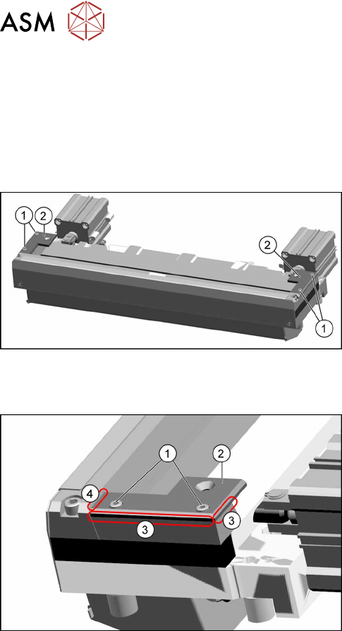
Fig.383: Removing the wiper clips
► Remove the two screws(1) (left and right) and
remove the wiper clips(2).
Installation
Fig.384: Installing the wiper clips
► Install the new wiper clips(2) on both sides and
loosely put the screws(1) back in.
► Align the wiper clips to the edges of the cutter
frame(3) and to the cutter top blade(4).
► Tighten the screws(1) fixing the wiper clips.
► Follow the removal instructions in reverse order for further installation.
See also
2 Replacing the Cutter on the COT Insert [03066690-xx] [}252]
11 Cutter
11.12 Replacing the Cutter Cable [03063590‑xx]
Service Manual SIPLACE TX Series 06/2017 273
11.12 Replacing the Cutter Cable [03063590‑xx]
Parts, equipment and tools
●
Cutter cable X-Series [03063590-xx]
Overview
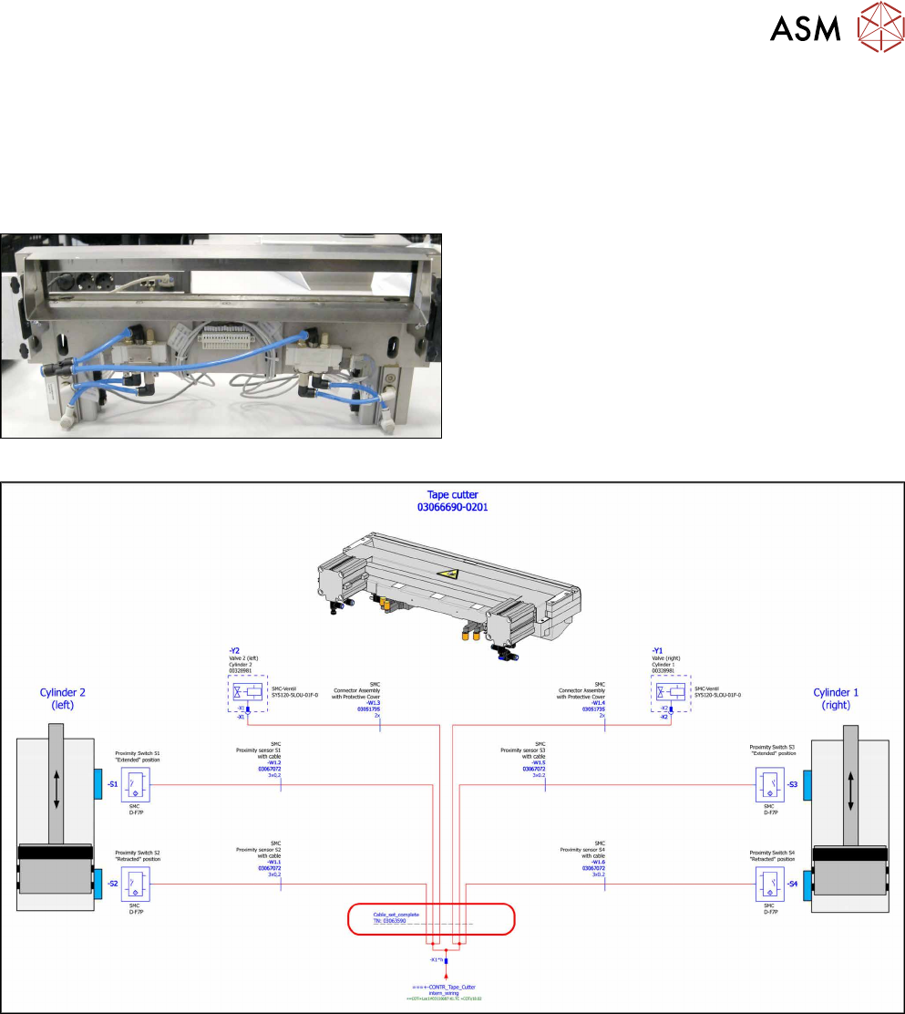
Fig.385: Cutter cable
Cutter cable on underside of cutter
Fig.386: Electrical connections
Removal
► Switch off the machine, disconnect it from the power supply and secure it to prevent
unauthorized reactivation. Observe the instructions in section 1.2 "Preparatory Work..." [}15].
► Disconnect all sensors and plugs and remove the cable set completely.
Mark the position of old sensors, especially the sensors responsible for positioning the short-
stroke cylinders.
Installation
► Fit the new cable set and adjust the sensors to the correct position.
► Follow the removal instructions in reverse order for further installation.
► Attach cables ties if necessary (strain relief).