00198150-02_SM_TX_en.pdf - 第273页
11 Cutter 11.12 Replacing the Cutter Cable [03063590‑xx] Service Manual SIPLACE TX Series 06/2017 273 11.12 Replacing the Cutter Cable [03063590‑xx] Parts, equipment and tools ● Cutter cable X-Series [03063590-xx] Overvi…
11 Cutter
11.11 Replacing Wiper Clip
272 Service Manual SIPLACE TX Series 06/2017
Removal
► Switch off the machine, disconnect it from the power supply and secure it to prevent
unauthorized reactivation. Observe the instructions in section 1.2 "Preparatory Work..." [}15].
► Remove the cutter from the machine.
Replacing the Cutter on the COT Insert [03066690-xx] [}252]
► Remove the wiper (see 11.10 "Replacing Wiper [03000491-xx]" [}270]).
Fig.383: Removing the wiper clips
► Remove the two screws(1) (left and right) and
remove the wiper clips(2).
Installation
Fig.384: Installing the wiper clips
► Install the new wiper clips(2) on both sides and
loosely put the screws(1) back in.
► Align the wiper clips to the edges of the cutter
frame(3) and to the cutter top blade(4).
► Tighten the screws(1) fixing the wiper clips.
► Follow the removal instructions in reverse order for further installation.
See also
2 Replacing the Cutter on the COT Insert [03066690-xx] [}252]
11 Cutter
11.12 Replacing the Cutter Cable [03063590‑xx]
Service Manual SIPLACE TX Series 06/2017 273
11.12 Replacing the Cutter Cable [03063590‑xx]
Parts, equipment and tools
●
Cutter cable X-Series [03063590-xx]
Overview
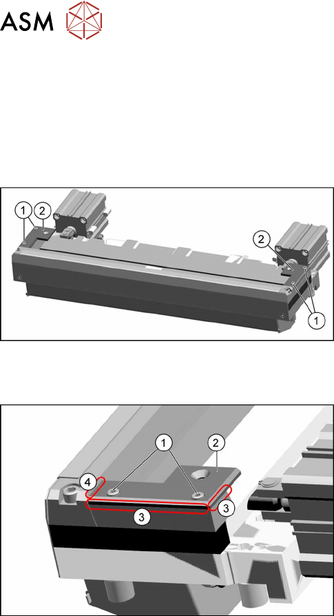
Fig.385: Cutter cable
Cutter cable on underside of cutter
Fig.386: Electrical connections
Removal
► Switch off the machine, disconnect it from the power supply and secure it to prevent
unauthorized reactivation. Observe the instructions in section 1.2 "Preparatory Work..." [}15].
► Disconnect all sensors and plugs and remove the cable set completely.
Mark the position of old sensors, especially the sensors responsible for positioning the short-
stroke cylinders.
Installation
► Fit the new cable set and adjust the sensors to the correct position.
► Follow the removal instructions in reverse order for further installation.
► Attach cables ties if necessary (strain relief).
11 Cutter
11.13 Replacing the Throttle Valve [03000600-xx]
274 Service Manual SIPLACE TX Series 06/2017
11.13 Replacing the Throttle Valve [03000600-xx]
Parts, equipment and tools
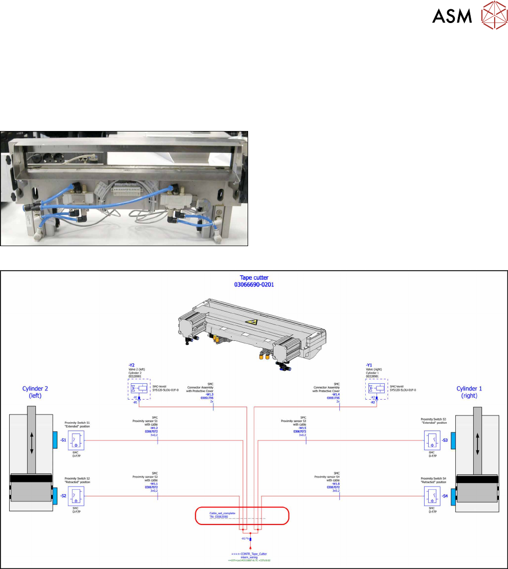
Fig.387: Throttle valve
●
Throttle valve AS2201F-02-06SA [03000600-xx]
Overview
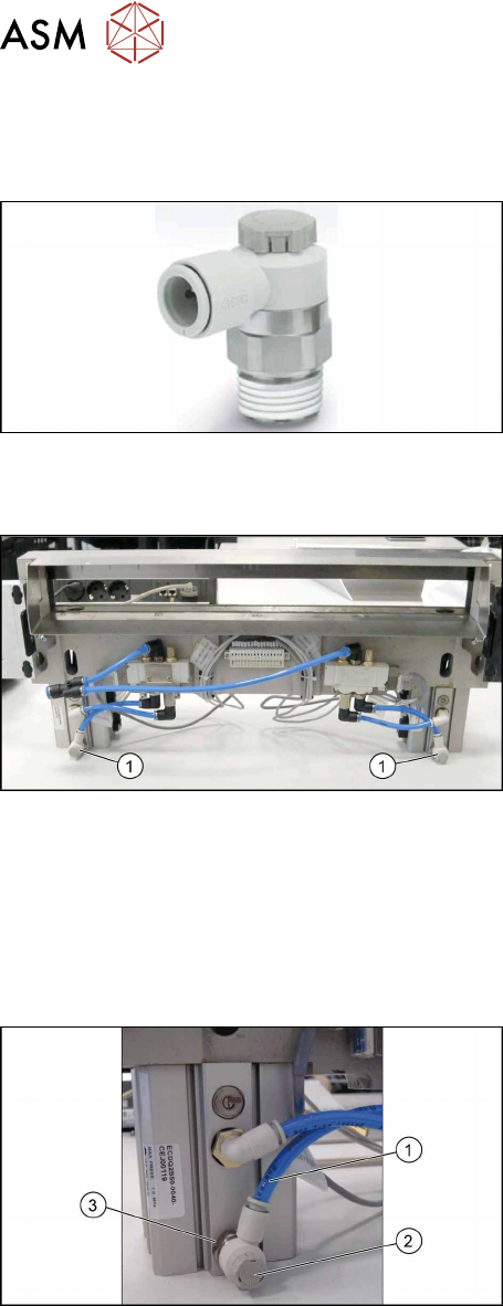
Fig.388: Throttle valves on cutter
1. Throttle valves
The throttle valves are installed at the lower sides of the
short-stroke cylinders.
Removal
► Switch off the machine, disconnect it from the power supply and secure it to prevent
unauthorized reactivation. Observe the instructions in section 1.2 "Preparatory Work..." [}15].
► Try to perform the exchange on the installed cutter.
If access is too limited, remove the cutter from the machine:
11.3 "Replacing the Cutter on the COT Insert [03066690-xx]" [}252]
Fig.389: Removing the throttle valve
► Disconnect the air tube(1) from the throttle valve(2).
► Turn the throttle valve in the direction "-" and count
the turns. Note the number.
► Remove the throttle valve by using a SW17 span-
ner(3).
Installation
► Fit the new throttle valve. Take care of the silicon sealing.
► Close the throttle valve completely in direction "-" and open it again in direction “+” by counting
the noted turnings.
This will ensure a working pre-adjustment for starting the final setting later on.
► Connect the air tube.
► Follow the removal instructions in reverse order for further installation.
► Set the new throttle valve (see below).