00198150-02_SM_TX_en.pdf - 第279页
12 SIPLACE TX-Series Component Trolley 12.1 SIPLACE TX-Series Component Trolley - Overview Service Manual SIPLACE TX Series 06/2017 279 12 SIPLACE TX-Series Component Trolley DANGER Observe User Manual ► Please observe t…

11 Cutter
11.15 Replacing the Silencer [00310744-xx]
278 Service Manual SIPLACE TX Series 06/2017
12 SIPLACE TX-Series Component Trolley
12.1 SIPLACE TX-Series Component Trolley - Overview
Service Manual SIPLACE TX Series 06/2017 279
12 SIPLACE TX-Series Component Trolley
DANGER
Observe User Manual
► Please observe the safety instructions in the user manual for all work!
12.1 SIPLACE TX-Series Component Trolley - Overview
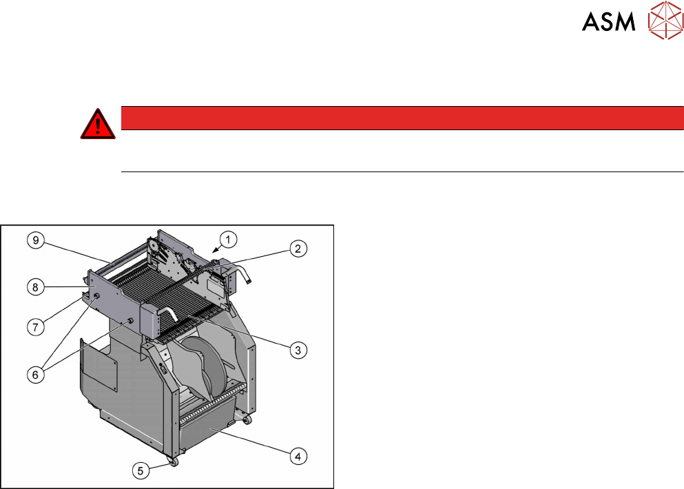
Fig.395: Component trolley overview
1. Actuator/protective bracket
12.6 "Replacing the Actuator/Protective
Bracket" [}284]
2. Feeder centering
12.7 "Replacing the Feeder Centering
[03028910-xx]" [}285]
3. Guide profile (Ω profile) and
feeder entering guide
12.4 "Replacing the Guide Profile/Entering Guide
Feeder" [}282]
12.4 "Replacing the Guide Profile/Entering Guide
Feeder" [}282]
4. Tape waste container
5. Reels
12.2 "Replacing the Rollers" [}280]
6. Bearing assembly
12.5 "Replacing the Bearing Assembly (Centering
Sleeve) [03103947-xx]" [}283]
7. Locking latch
12.3 "Replacing the Locking Latch [03069205-
xx]" [}280]
8. Changeover table
9. Stop bar with centering holes
12 SIPLACE TX-Series Component Trolley
12.2 Replacing the Rollers
280 Service Manual SIPLACE TX Series 06/2017
12.2 Replacing the Rollers
Parts, equipment and tools
●
Front roller LDA-VPA 75K-EL-47994 [03004958-xx]
●
Back roller LPA-POA 50G [03121354-xx]
●
Second Person
Overview
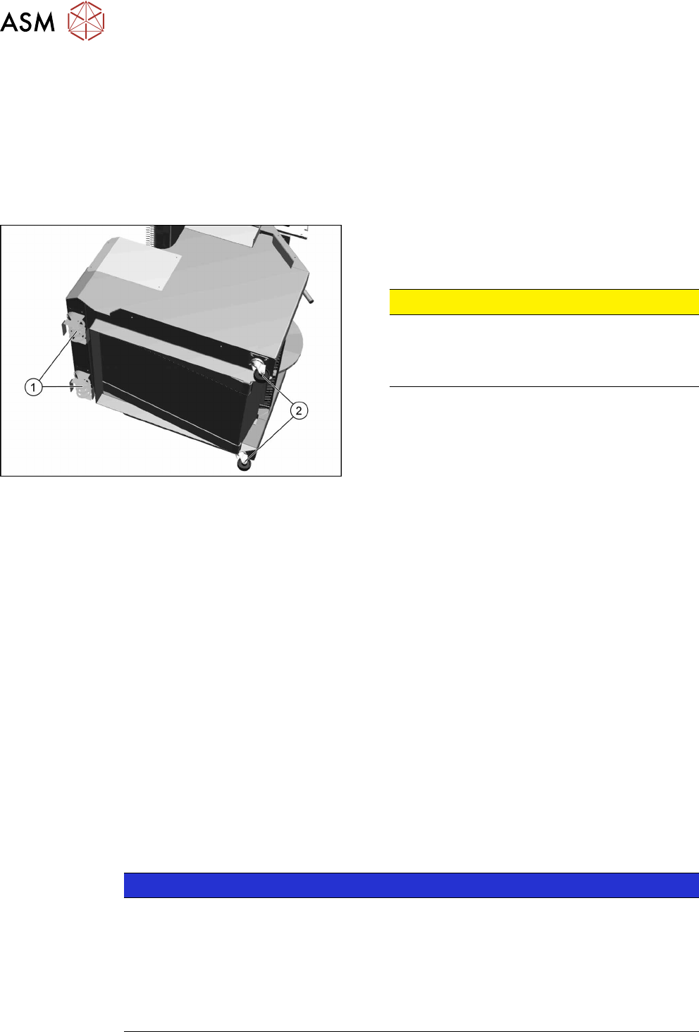
Fig.396: Rolls on COT
1. Back roller LPA-POA 50G [03121354-xx]
2. Front roller LDA-VPA 75K-EL-47994 [03004958-
xx]
CAUTION!
Heavy machine part!
The component trolley must be placed on one
side in order to remove the rollers. You will need
two people to perform this task.
.
Removal
► Move the component trolleys out of the machine.
► Remove all feeders.
► Place the component trolley on its side on a suitable surface.
► Remove the fastening screws on the roller to be replaced
► Remove the roller.
Installation
► Fit the new roller.
► Stand the component trolley on its wheels again.
12.3 Replacing the Locking Latch [03069205-xx]
Parts, equipment and tools
●
Single locking latch [03069205-xx]
●
Tension spring [03010352-xx]
●
Cover plate for locking strip [03077142-xx]
NOTICE
SIPLACE TX/X/SX Series Component Trolley
Component trolleys from the SIPLACE TX, SX and X-Series (S) require a locking latch for
each feeder track.
► Feeder lock [03023777-xx] with 40 locking latches
(1x per component trolley SIPLACE TX/X-Series (S)/SX4)
ð The feeder lock can also be completely dismantled from the component trolley and
replaced.