00198150-02_SM_TX_en.pdf - 第280页
12 SIPLACE TX-Series Component Trolley 12.2 Replacing the Rollers 280 Service Manual SIPLACE TX Series 06/2017 12.2 Replacing the Rollers Parts, equipment and tools ● Front roller LDA-VPA 75K-EL-47994 [03004958-xx] ● Bac…
12 SIPLACE TX-Series Component Trolley
12.1 SIPLACE TX-Series Component Trolley - Overview
Service Manual SIPLACE TX Series 06/2017 279
12 SIPLACE TX-Series Component Trolley
DANGER
Observe User Manual
► Please observe the safety instructions in the user manual for all work!
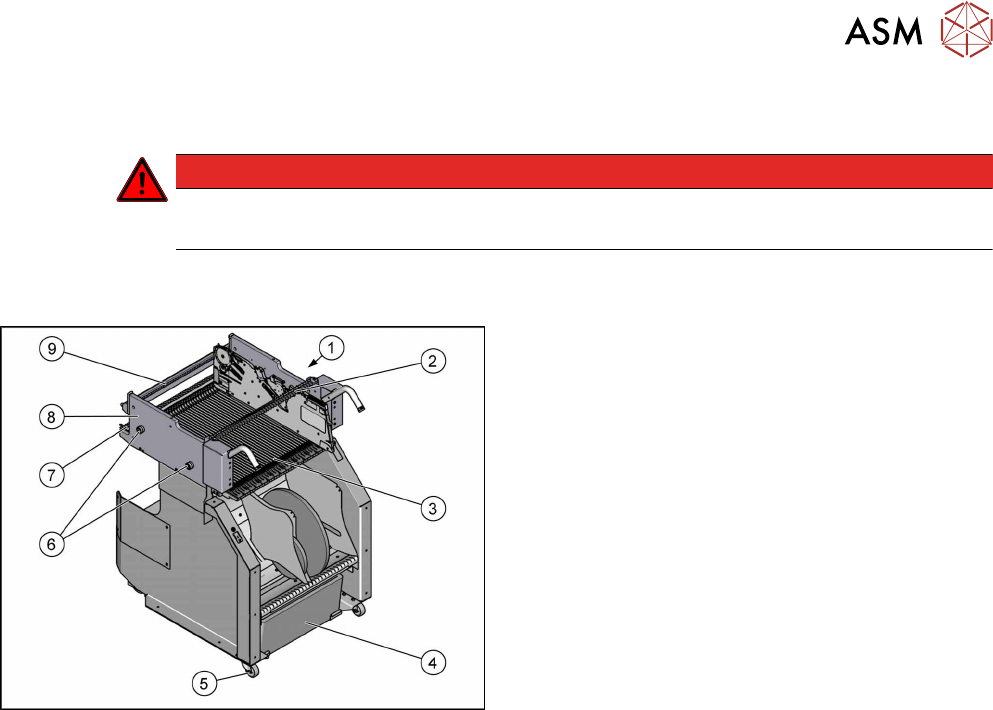
12.1 SIPLACE TX-Series Component Trolley - Overview
Fig.395: Component trolley overview
1. Actuator/protective bracket
12.6 "Replacing the Actuator/Protective
Bracket" [}284]
2. Feeder centering
12.7 "Replacing the Feeder Centering
[03028910-xx]" [}285]
3. Guide profile (Ω profile) and
feeder entering guide
12.4 "Replacing the Guide Profile/Entering Guide
Feeder" [}282]
12.4 "Replacing the Guide Profile/Entering Guide
Feeder" [}282]
4. Tape waste container
5. Reels
12.2 "Replacing the Rollers" [}280]
6. Bearing assembly
12.5 "Replacing the Bearing Assembly (Centering
Sleeve) [03103947-xx]" [}283]
7. Locking latch
12.3 "Replacing the Locking Latch [03069205-
xx]" [}280]
8. Changeover table
9. Stop bar with centering holes
12 SIPLACE TX-Series Component Trolley
12.2 Replacing the Rollers
280 Service Manual SIPLACE TX Series 06/2017
12.2 Replacing the Rollers
Parts, equipment and tools
●
Front roller LDA-VPA 75K-EL-47994 [03004958-xx]
●
Back roller LPA-POA 50G [03121354-xx]
●
Second Person
Overview
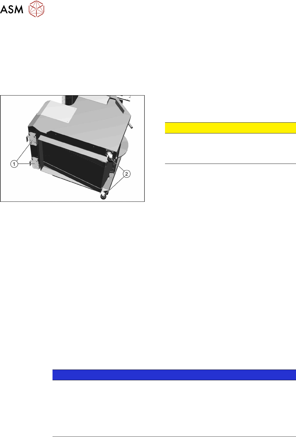
Fig.396: Rolls on COT
1. Back roller LPA-POA 50G [03121354-xx]
2. Front roller LDA-VPA 75K-EL-47994 [03004958-
xx]
CAUTION!
Heavy machine part!
The component trolley must be placed on one
side in order to remove the rollers. You will need
two people to perform this task.
.
Removal
► Move the component trolleys out of the machine.
► Remove all feeders.
► Place the component trolley on its side on a suitable surface.
► Remove the fastening screws on the roller to be replaced
► Remove the roller.
Installation
► Fit the new roller.
► Stand the component trolley on its wheels again.
12.3 Replacing the Locking Latch [03069205-xx]
Parts, equipment and tools
●
Single locking latch [03069205-xx]
●
Tension spring [03010352-xx]
●
Cover plate for locking strip [03077142-xx]
NOTICE
SIPLACE TX/X/SX Series Component Trolley
Component trolleys from the SIPLACE TX, SX and X-Series (S) require a locking latch for
each feeder track.
► Feeder lock [03023777-xx] with 40 locking latches
(1x per component trolley SIPLACE TX/X-Series (S)/SX4)
ð The feeder lock can also be completely dismantled from the component trolley and
replaced.
12 SIPLACE TX-Series Component Trolley
12.3 Replacing the Locking Latch [03069205-xx]
Service Manual SIPLACE TX Series 06/2017 281
Overview
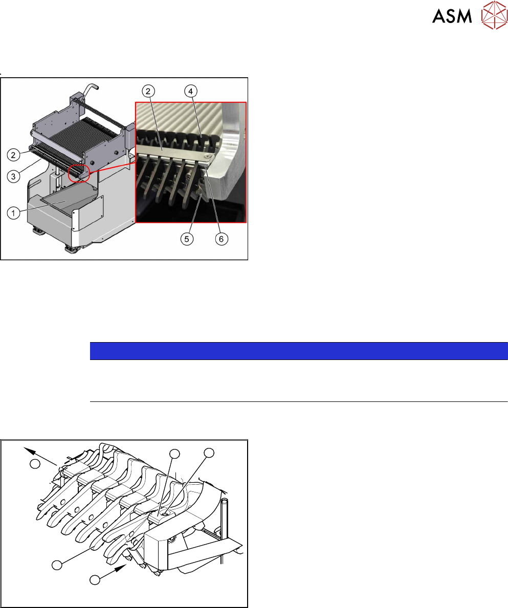
Fig.397: Locking latch on component trolley
1. Tape waste container
2. Operation cover
3. Position of complete feeder locking mechanism
4. Locking latch
5. Tension spring
6. Pressure plate (under cover(2))
Removal / Installation
► Remove the waste tape container (1) and empty it.
► Refit the waste tape container. This makes sure that any parts which fall down are not lost.
NOTICE
Waster tape container
You can use the waste tape container as a surface on which to place small parts e.g. ten-
sion springs, locking latches etc.
► Remove the screws fastening the cover plate locking rail [03077142-xx](2). Use a suitable
Phillips screwdriver to avoid damaging the screws.
4
5
1
3
2
Fig.398: Removing locking latch
► Unhook all tension springs (1) from the locking
latches (2).
► Remove the screws (3) fastening the pressure
plates(4).
► Pull out the locking latches with the shaft(5).
► The locking latches can now be pushed off the
shaft.
► Return the locking latches, including the new
one, to the shaft.
► Fit the locking latches and shaft.
► During reassembly, take care to keep the pressure plates in their correct position (4). These
are not symmetrical and will not hold the shaft properly if placed in a certain (incorrect) posi-
tion.
► When tightening the fastening screws (3), make sure that the pressure plates (4) are not at an
incorrect angle and that the locking latches do not jam.
► Hook the tension springs (1) back up.
► Refit the cover.