00198150-02_SM_TX_en.pdf - 第283页
12 SIPLACE TX-Series Component Trolley 12.5 Replacing the Bearing Assembly (Centering Sleeve) [03103947-xx] Service Manual SIPLACE TX Series 06/2017 283 12.5 Replacing the Bearing Assembly (Centering Sleeve) [03103947-xx…
12 SIPLACE TX-Series Component Trolley
12.4 Replacing the Guide Profile/Entering Guide Feeder
282 Service Manual SIPLACE TX Series 06/2017
12.4 Replacing the Guide Profile/Entering Guide Feeder
Parts, equipment and tools
Select the required spare part:
●
Short guide profile [03002898-xx]
●
Insert feeder [03039368-xx]
Overview
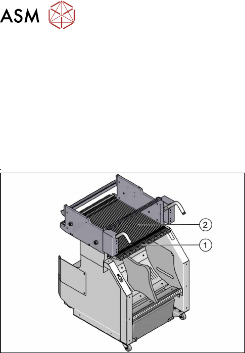
Fig.399: Guide profiles on component trolley
1. Short guide profile
2. Feeder entering guide
The short guide profiles are fixed from above with one
screw each.
The feeder entering guide is fixed from below with four
screws each.
12 SIPLACE TX-Series Component Trolley
12.5 Replacing the Bearing Assembly (Centering Sleeve) [03103947-xx]
Service Manual SIPLACE TX Series 06/2017 283
12.5 Replacing the Bearing Assembly (Centering Sleeve)
[03103947-xx]
Parts, equipment and tools
●
Bearing assembly [03103947-xx]
●
Loctite 243 [00334892‑xx]
NOTICE
Always replace all bearing assemblies
We recommend that you always replace all bearing assemblies belonging to a changeover
table at the same time.
Overview
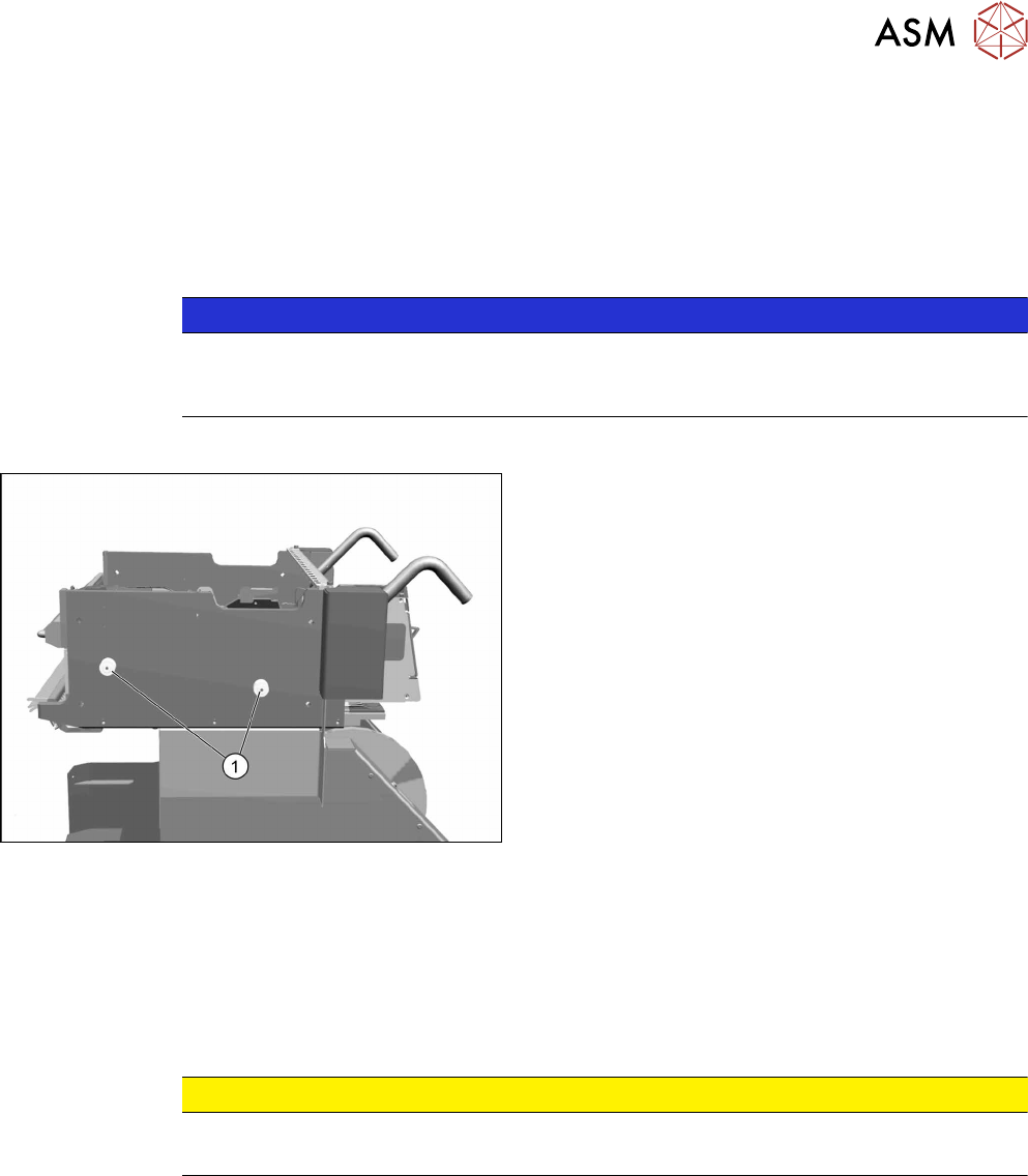
Fig.400: Bearing assemblies on component trolley
1. Bearing assemblies (fourper table)
Removal
► Remove the screw fastening the bearing assembly and then remove the centering sleeve.
Installation
► Follow the removal instructions in reverse order for installation. Also observe the following in-
structions:
CAUTION
Installation instructions
► Secure the screws with Loctite 243.
12 SIPLACE TX-Series Component Trolley
12.6 Replacing the Actuator/Protective Bracket
284 Service Manual SIPLACE TX Series 06/2017
12.6 Replacing the Actuator/Protective Bracket
Parts, equipment and tools
●
Torx screwdriver ESD 1.0-5.0 Nm [03078400-xx]
●
Bit holder for TorqueVario screwdriver [03078706-xx]
●
Bit 1/4, TX20 with hole drilled [03148413‑xx]
●
Safety switch D4DS-K3 [03107666-xx]
●
Protective bracket: holder and protector for actuator [03126075-xx]
Overview
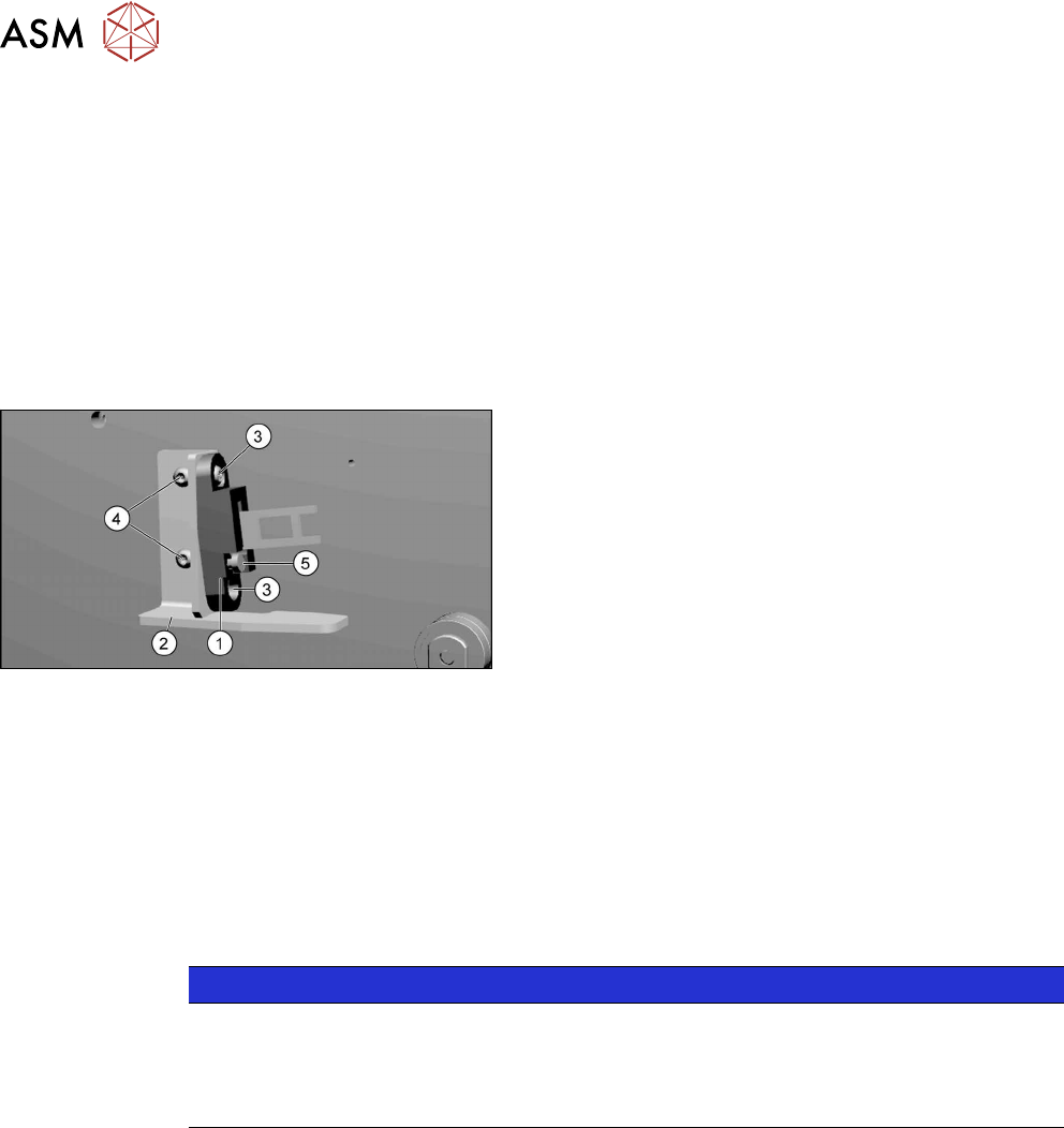
Fig.401: Actuator and protective bracket on component trol-
ley
1. actuator
2. Protective bracket
3. Two fastening screws actuator
4. Two fastening screws protective bracket
5. Adjustment screw for actuator angle
Removal
► Remove the fastening screws of the actuator/protective bracket.
► Remove the actuator/protective bracket.
Installation
► Follow the removal instructions in reverse order for further installation. Also observe the fol-
lowing instructions:
NOTICE
Installation instructions
► Tighten the fastening screws for the actuator on the protective bracket with a max-
imum torque of 2.0Nm.
► Set the actuator (see below).
See also
2 Setting the Actuator on the Component Trolley [}285]