00198150-02_SM_TX_en.pdf - 第287页
13 Docking Station for Component Trolley 13.1 Docking Station for Component Trolley - Overview Service Manual SIPLACE TX Series 06/2017 287 13 Docking Station for Component Trolley DANGER Observe User Manual ► Please obs…

12 SIPLACE TX-Series Component Trolley
12.7 Replacing the Feeder Centering [03028910-xx]
286 Service Manual SIPLACE TX Series 06/2017
13 Docking Station for Component Trolley
13.1 Docking Station for Component Trolley - Overview
Service Manual SIPLACE TX Series 06/2017 287
13 Docking Station for Component Trolley
DANGER
Observe User Manual
► Please observe the safety instructions in the user manual for all work!
NOTICE
Retrofit kit for TX-Series
The X-Series docking station can be retrofitted for user with TX-Series component trolleys.
► For more details, read the technical information "Conversion kit for TX component trol-
ley docking station" [DE:TI2017‑01D02] [EN:TI2017‑01E02].
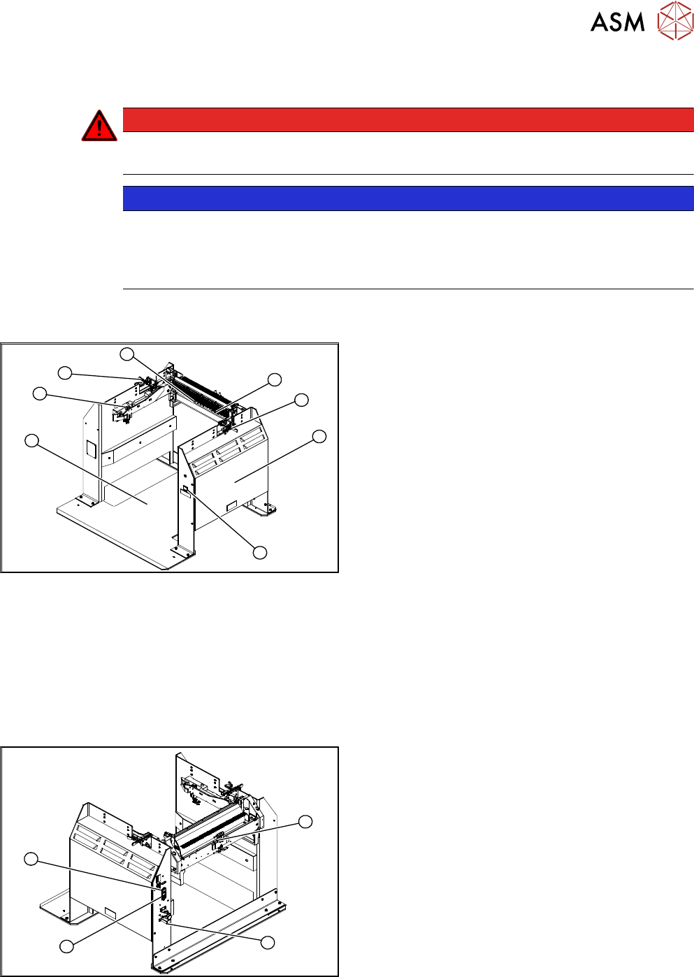
13.1 Docking Station for Component Trolley - Overview
3
4
1
7
6
5
4
2
Fig.404: Docking station – overview 1
1. Docking station – assembly [00116933-xx]
2. Unlocking pushbutton [00334095-xx]
13.10 "Replacing the Unlocking Pushbutton
[00334095-xx]" [}296]
3. Power pack and pressure control valve for
locking cylinder (behind the cover)
13.2 "Replacing the Power Pack
[03121806-xx]" [}288]
4. Locking lever [03025104-xx]
13.5 "Replacing the Locking Lever
[03025104-XX]" [}291]
5. Feeder unlocking device 40-fold [03011582-XX]
13.7 "Replacing the 40-Fold Feeder Unlock
Device [03011582-xx]" [}293]
6. Feeder Control Unit (FCU)
13.8 "Replacing the Feeder Control Unit (FCU)
[03059623Sxx]" [}294]
7. Short-stroke cylinder for locking unit
[03034831‑xx]
13.4 "Replacing the Locking Unit Short-Stroke
Cylinder [03034831-xx]" [}290]
1
4
3
2
Fig.405: Docking station – overview 2
1. Control valve [03003489-xx]
13.11 "Replacing the Control Valve [03003489-
xx]" [}297]
2. ON/OFF switch
3. Microfuse [03033387-xx]
13.3 "Replacing the Microfuse [03033387-
xx]" [}289]
4. Pressure control valve for bulkcase feeder and
main connection (5.5 bar)
●
13.6 "Replacing the Positions End Switch of
the Component Trolley Locking Device
[03033395-xx]" [}292]
●
13.9 "Replacing the Complete Coupling - Earth-
ing and Compressed Air for the Bulk
Case" [}295]
13 Docking Station for Component Trolley
13.2 Replacing the Power Pack [03121806-xx]
288 Service Manual SIPLACE TX Series 06/2017
13.2 Replacing the Power Pack [03121806-xx]
NOTICE
Observe the technical information
► Observe the technical information "Power pack for docking station for component trol-
ley SIPLACE X [116933] and SX [116965] has been discontinued" [DE: TI2015-04D07]
[EN: TI2015-04E07].
Parts, equipment and tools
●
Switching power supply RSP-500-27 [03121806‑xx] (replaces: [03025938‑xx])
●
Detailed circuit diagrams folder for SIPLACE TX-Series (up to no. 499) [DE+EN: 00197933-
xx]
●
Detailed circuit diagrams folder for SIPLACE TX-Series (from no. 500) [DE+EN: 00198274-xx]
Removal / installation
DANGER
Switch off the voltage supply
► Press the ON/OFF button to switch off and disconnect the power supply.
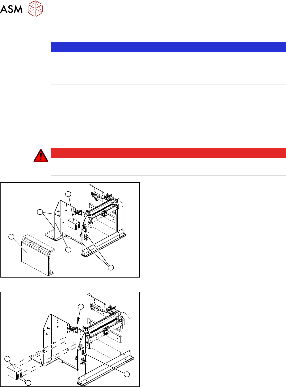
4
3
1
3
2
Fig.406: Removing the cover
1. Operation cover
2. Bar for clamping the cover
3. Four fastening screws
4. Power pack
► Remove the four screws (3) fastening the cover
(1). The cover is clamped in place with the help
of the bar(2).
► Pull the cover out of the docking station.
► Take care not to damage the earth connection.
4
3
1
2
Fig.407: Removing the power pack
► Disconnect all electrical connections(4) to the
power pack(3). You may want to mark their posi-
tions to make clear assignment easier later on.
► Remove the four screws (2) fastening the power
pack on the inside of the docking station.
► Connect all cables and fit the new power pack.
► Press the ON/OFF button(1) to switch on.
► Set the output voltage of the power pack at ter-
minals nine and twelve:
– Standard (without BulkFeeder):
26.8 V (+/- 0.5 V)
– When using the BulkFeeders the output
voltage is set permanently to
28.0V(+/‑0.5V).
► Refit the cover.