00198150-02_SM_TX_en.pdf - 第29页
2 Basic Machine 2.4 Replacing the Cover Service Manual SIPLACE TX Series 06/2017 29 Fig.16: Cover fan ► Unplug the cover fan cable (1) . ► Remove the cable ties (2) . Fig.17: Removing the cover WARNING! Hold the co…
2 Basic Machine
2.4 Replacing the Cover
28 Service Manual SIPLACE TX Series 06/2017
2.4 Replacing the Cover
Parts, equipment and tools
●
Choose the required part:
– Cover, long – location 1 TX [03118640‑xx]
– Cover, short – location 1 TX [03118601‑xx]
– Cover – location 2 [03117921-xx]
●
Second person
Overview
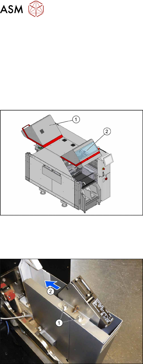
Fig.14: Cover.
1. Cover location 1
2. Cover location 2
Removal
► Switch off the machine, disconnect it from the power supply and secure it to prevent
unauthorized reactivation. Observe the instructions in section 1.2 "Preparatory Work..." [}15].
Fig.15: Screws at the cover switch
► Remove the two screws(1) fastening the cover
switch.
► Move the cover switch(2) towards the middle of
the machine, so it cannot be damaged by an un-
adjusted cover.
2 Basic Machine
2.4 Replacing the Cover
Service Manual SIPLACE TX Series 06/2017 29
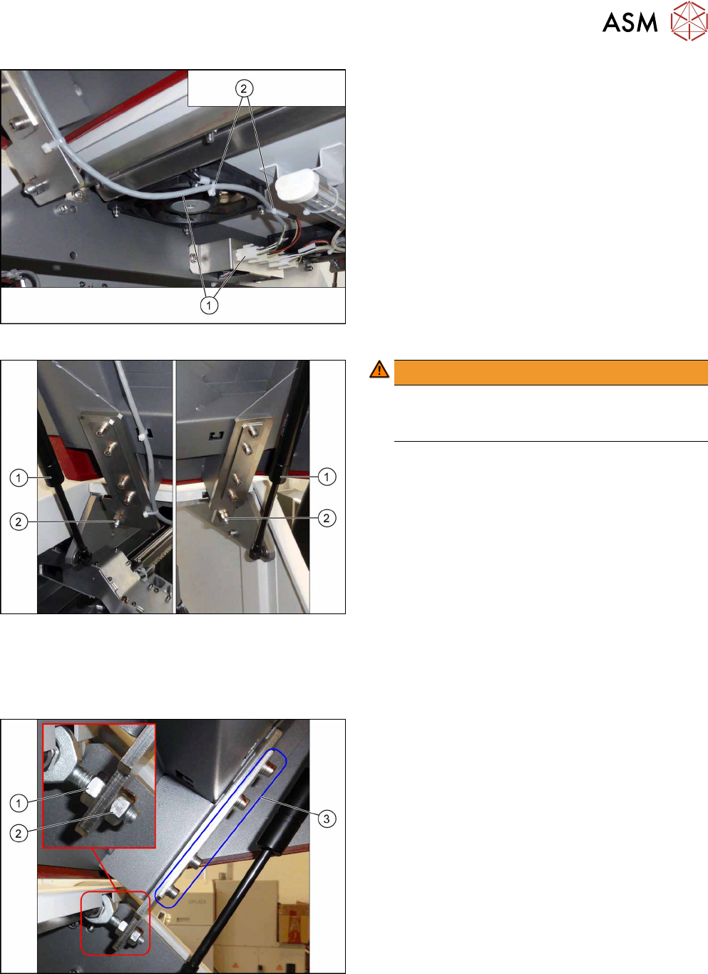
Fig.16: Cover fan
► Unplug the cover fan cable(1).
► Remove the cable ties(2).
Fig.17: Removing the cover
WARNING!
Hold the cover
Make sure a second person is holding the cover
when removing it in the following steps.
.
► Remove the two gas pressure shock ab-
sorbers(1) (see 2.2 "Replacing the Gas Pressure
Shock Absorber on the Cover" [}24]).
► Remove the two nuts(2)holding the machine
cover.
► Remove the cover.
Installation
► Follow the removal instructions in reverse order for installation. Also observe the following in-
structions:
Fig.18: Installation
Installation instructions:
► Set the protective machine cover.
Use the nuts(1) and(2) for adjusting the height.
Use the screws(3) for setting the left/right side
and the depth.
► Set the actuator for the cover (see below).
2 Basic Machine
2.4 Replacing the Cover
30 Service Manual SIPLACE TX Series 06/2017
2.4.1 Setting the Covers
2.4.1.1 Overview
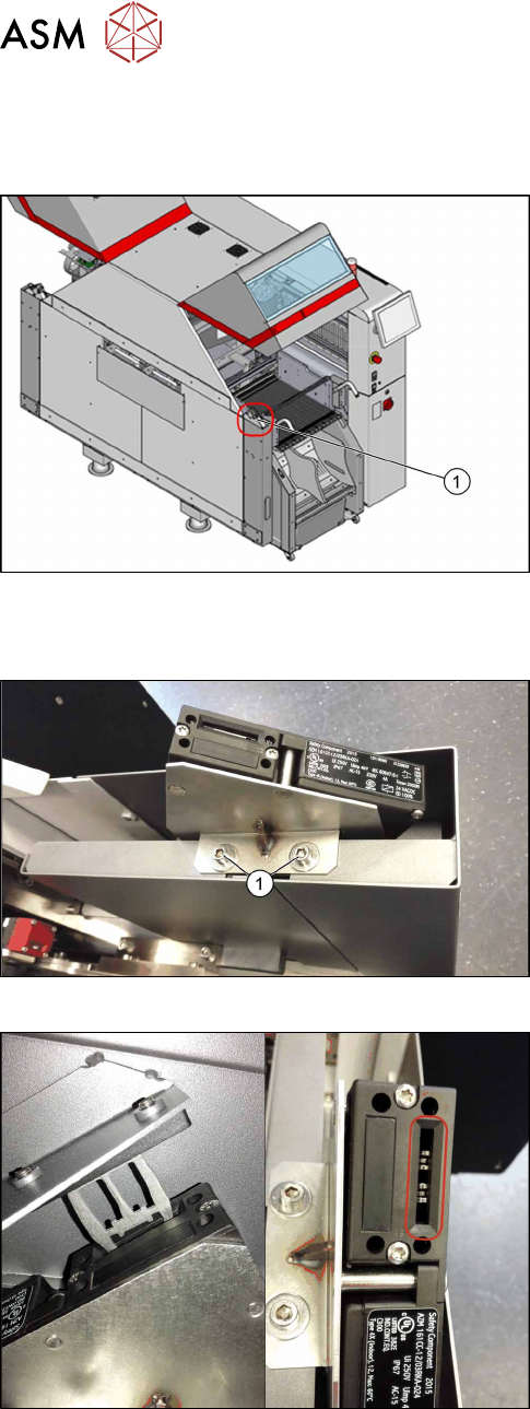
Fig.19: Cover switch
1. Cover switch
2.4.1.2 Adjusting the Cover Switch
Fig.20: Cover switch [03110691-xx]
► Loosen the screws(1) fastening the cover switch
to the bracket, so that the assembly can be easily
moved.
Fig.21: Cover switch
► Close the cover far enough for the actuator to be
just over the switch. Align them so that the metal
bracket is parallel to the opening in the switch.
The metal bracket may not scrape against the
cover switch.
► Tighten the cover switch screws in this position.