00198150-02_SM_TX_en.pdf - 第290页
13 Docking Station for Component Trolley 13.4 Replacing the Locking Unit Short-Stroke Cylinder [03034831-xx] 290 Service Manual SIPLACE TX Series 06/2017 13.4 Replacing the Locking Unit Short-Stroke Cylinder [03034831-xx…
13 Docking Station for Component Trolley
13.3 Replacing the Microfuse [03033387-xx]
Service Manual SIPLACE TX Series 06/2017 289
13.3 Replacing the Microfuse [03033387-xx]
Parts, equipment and tools
●
Microfuse [03033387-xx]
Overview
1
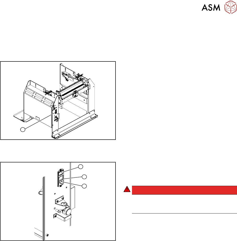
Fig.408: Microfuse on docking station
1. Position of microfuse (T 8.0 A)
Replacing the micro switch
1
3
2
Fig.409: Replacing the Micro Switch
1. Cover on the microfuse (T8.0A)
2. ON / OFF switch
3. Power supply plug
DANGER!
Switch off the voltage supply
Press the ON/OFF button (2) to switch off and
then unplug the power supply (3).
.
► Open the cover (1) on the microfuse.
► Remove the microfuse.
► Insert the new microfuse and close the cover (1).
► Connect the connection cable (3) and press the ON/OFF button to switch on (2).
13 Docking Station for Component Trolley
13.4 Replacing the Locking Unit Short-Stroke Cylinder [03034831-xx]
290 Service Manual SIPLACE TX Series 06/2017
13.4 Replacing the Locking Unit Short-Stroke Cylinder
[03034831-xx]
Parts, equipment and tools
●
Short-stroke cylinder [03034831-xx]
Overview
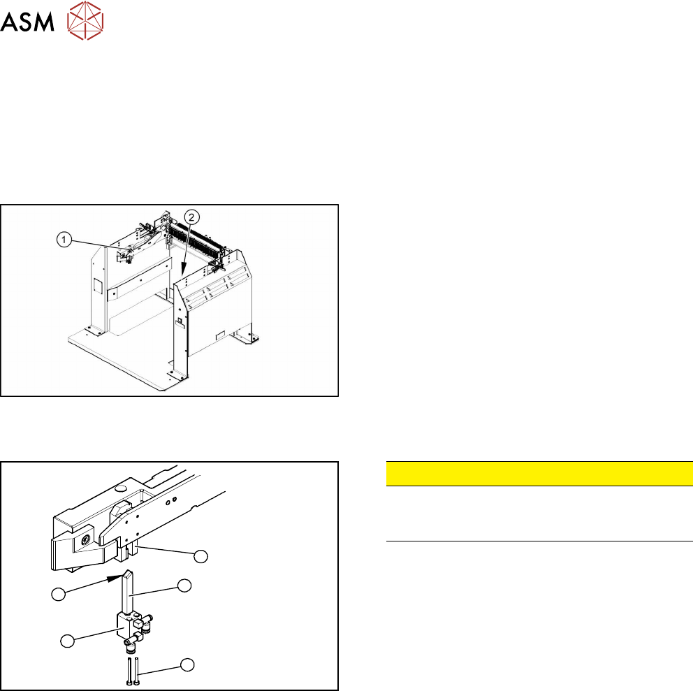
Fig.410: Locking unit left and right
1. Installation position of left locking unit
2. Installation position of right locking unit
Removal
5
1
4
3
2
Fig.411: Removing the locking unit
CAUTION!
Risk of injury
Risk of injury when disconnecting pressurized
compressed air lines.
.
► Switch off the compressed air supply.
► Remove the pneumatic connections on the short-
stroke cylinder.
► Remove the two screws (1) fastening the short-
stroke cylinder (2).
► Pull the short-stroke cylinder (2) and the locking
slider(3) downwards and out of the guidance
block(5).
► Unscrew the locking slider (3) from the short-
stroke cylinder (2).
Installation
► Install the locking slider (3) on the new short-stroke cylinder (2).
► Clean the locking sliders (3) and the guidance block (5) with a clean, lint-free cloth and lubric-
ate both slightly with Unisilikon.
► Move the locking slider (3) into the guidance block, so that the beveled side (4) is pointing to
the front (in the direction of travel). This is important when moving the component trolley in.
► Fit the short-stroke cylinder with the two fastening screws.
► Reconnect to the compressed air supply.
► Switch the compressed air supply on and check that the left and right locking sliders move out
at the same time.
► If necessary, adjust the throttle valve (6) on the short-stroke cylinder.
13 Docking Station for Component Trolley
13.5 Replacing the Locking Lever [03025104-XX]
Service Manual SIPLACE TX Series 06/2017 291
13.5 Replacing the Locking Lever [03025104-XX]
Parts, equipment and tools
●
Horizontal tensioner DE-STA-CO 225-U [03025104-xx]
Overview
1
2
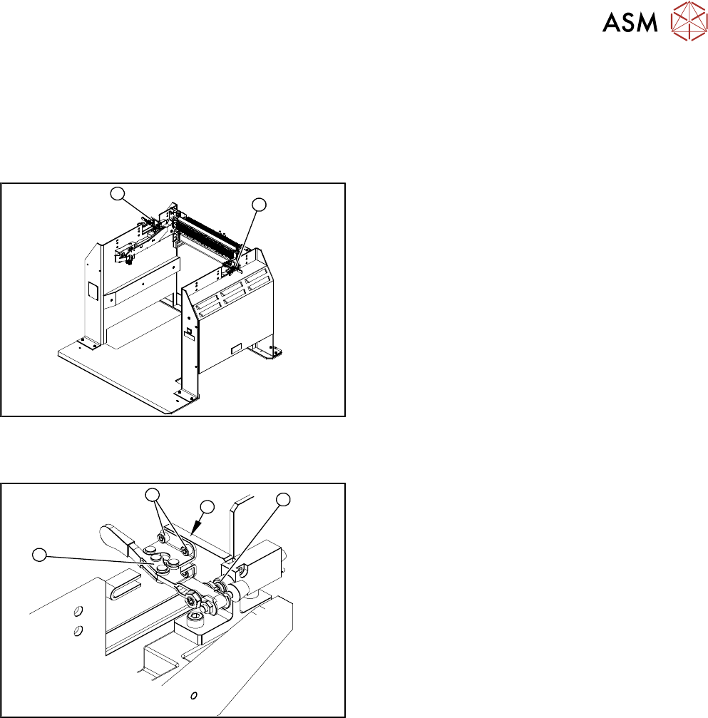
Fig.412: Locking lever left and right
1. Locking lever – on the left side
2. Locking lever – on the right side
Removal
4
3
2
1
Fig.413: Removing the locking lever
1. Locking lever
2. Four fastening screws
3. Position end switch
4. Limit switch
► Remove the four screws(2) (twoeach at the top
and bottom) fastening the locking lever(1).
► Remove the locking lever.
Installation
► Loosely screw in the new locking lever.
► Align the locking lever to the edge (3) and tighten the four fastening screws.
► Check that the limit switch (4) is actuated when the locking lever is closed. Correct the posi-
tion of the locking lever if necessary.
► Check the position end switch function, by trying out the locking procedure.