00198150-02_SM_TX_en.pdf - 第295页
13 Docking Station for Component Trolley 13.9 Replacing the Complete Coupling - Earthing and Compressed Air for the Bulk Case Service Manual SIPLACE TX Series 06/2017 295 13.9 Replacing the Complete Coupling - Earthing a…
13 Docking Station for Component Trolley
13.8 Replacing the Feeder Control Unit (FCU) [03059623Sxx]
294 Service Manual SIPLACE TX Series 06/2017
13.8 Replacing the Feeder Control Unit (FCU) [03059623Sxx]
Parts, equipment and tools
●
X-FCU, X-Series [03059623Sxx] (replaces: [03020068-xx])
NOTICE
Replacing the old FCU with a new one
If an old FCU is being replaced with a new one, the docking station will need an additional
"cable set X-FCU for docking station X 116933" [03098897-xx].
► For more information, read the technical information "Replacing the FCU" (X-Series,
SX4/DX4, X-Series S) [DE: TI2014-11D15] [EN: TI2014-11E15].
Overview
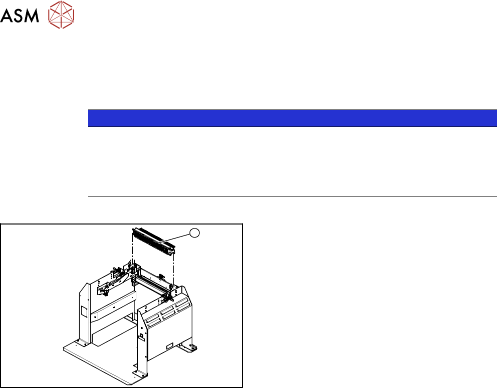
1
Fig.417: FCU on docking station
1. Feeder control unit
Removal / installation
The FCU is the same assembly used in the COT insert. The service work is identical with the pro-
cedure used for the COT insert. All necessary service work is described there.
See also
2 Replacing the Feeder Control Unit (FCU) [}241]
13 Docking Station for Component Trolley
13.9 Replacing the Complete Coupling - Earthing and Compressed Air for the Bulk Case
Service Manual SIPLACE TX Series 06/2017 295
13.9 Replacing the Complete Coupling - Earthing and
Compressed Air for the Bulk Case
Parts, equipment and tools
You can either replace the individual coupling socket or the complete coupling unit for ground and
compressed air.
●
Coupling socket for compressed air coupling [03017026-xx]
●
Coupling assembly for ground and compressed air [03017025-xx]
Overview
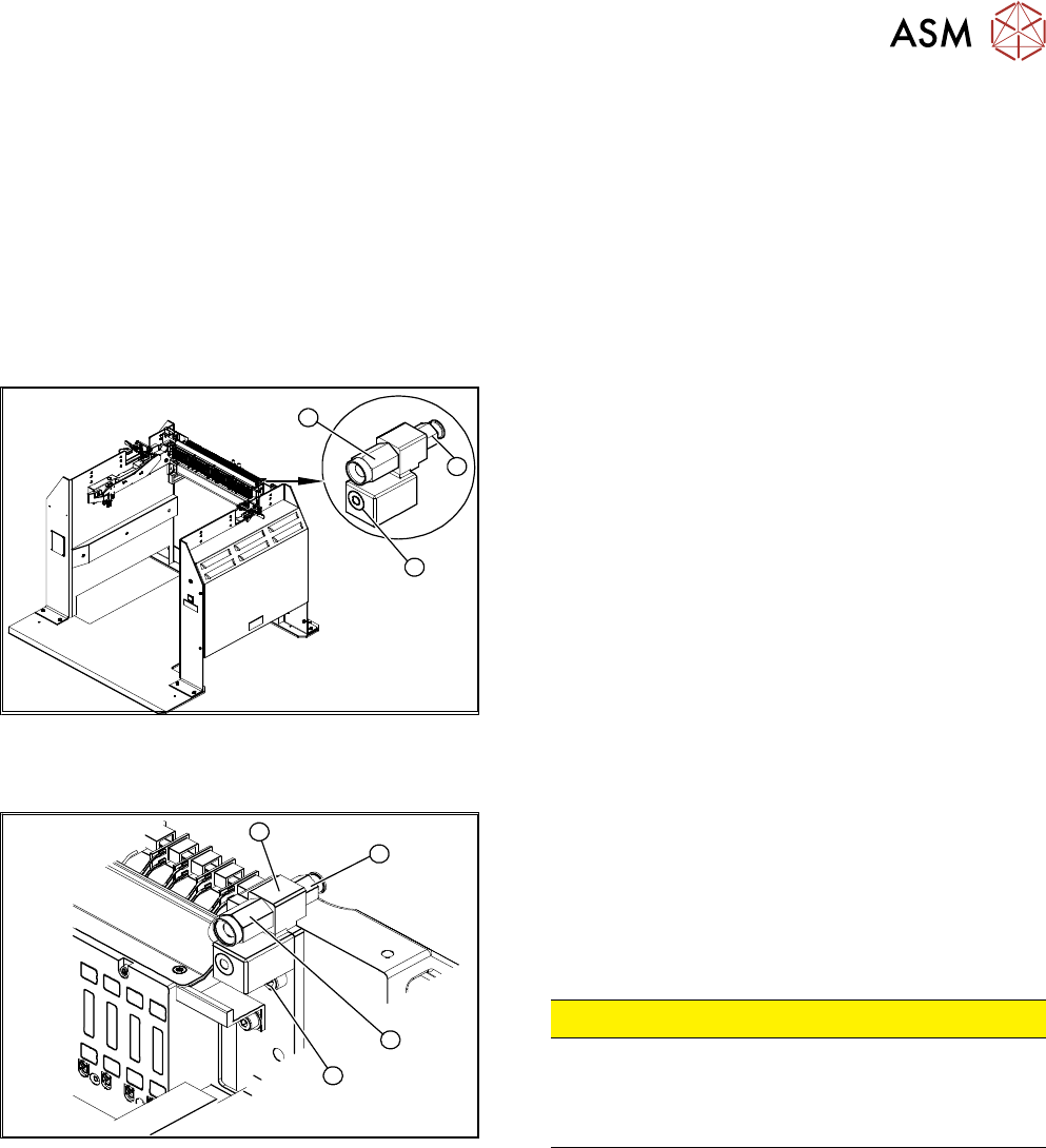
3
1
2
Fig.418: Coupling on docking station
1. Coupling socket for component trolley compressed
air coupling (bulkcase feeder)
2. Compressed air connection to the pneumatic control
value 5.5 bar.
3. Component trolley ground coupling (bulkcase
feeder)
Removal / installation
3
2
4
1
Fig.419: Removing the coupling
1. Fastening the complete coupling (ground and com-
pressed air)
2. Coupling socket for compressed air coupling
3. Mount
4. Pneumatic connection to pressure control valve 5.5
bar at the back
CAUTION!
Risk of injury from compressed air!
Risk of injury when disconnecting pressurized com-
pressed air lines.
Switch off the compressed air supply.
.
Individual Replacement of Coupling Socket for Compressed Air Coupling
► Unplug the compressed air connection.
► Use an open-end wrench to unscrew the coupling socket from its mount.
► Screw in the new coupling socket and connect the compressed air supply.
► Switch on the compressed air supply.
► Check the set pressure of 5.5 bar at the pressure control valve (located at the back).
Replacing the Complete Coupling for Ground and Compressed Air
► Unplug the compressed air connection.
► Remove the fastening screw and remove the complete unit.
► Fit the new assembly and reconnect the compressed air supply.
► Switch on the compressed air supply.
► Check the set pressure of 5.5 bar at the pressure control valve (located at the back).
13 Docking Station for Component Trolley
13.10 Replacing the Unlocking Pushbutton [00334095-xx]
296 Service Manual SIPLACE TX Series 06/2017
13.10 Replacing the Unlocking Pushbutton [00334095-xx]
Parts, equipment and tools
●
Unlocking pushbutton [00334095-xx]
Overview
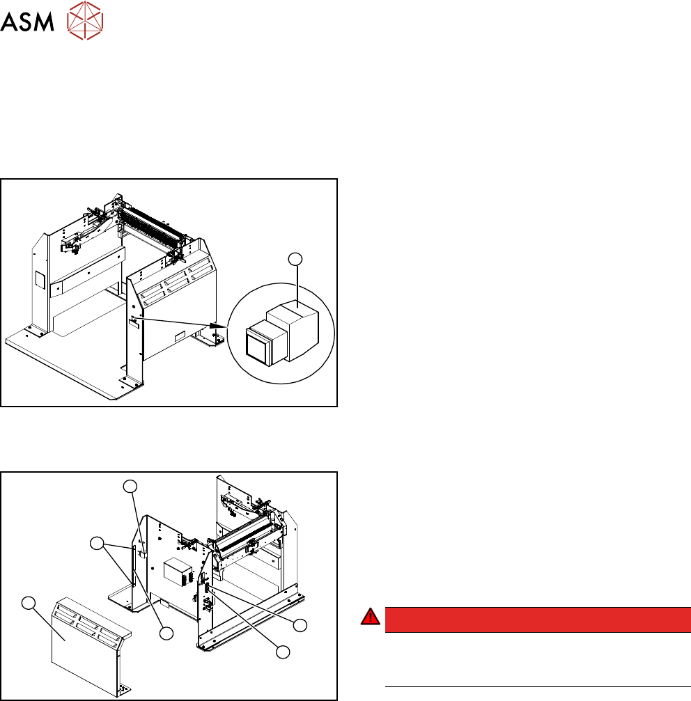
1
Fig.420: Unlocking pushbutton on docking station
1. Unlocking pushbutton
Removal / installation
4
6
5
1
3
2
Fig.421: Removing the unlocking pushbutton
1. ON / OFF switch
2. Power supply plug
3. Cover
4. Bar for clamping the cover
5. Four screws fastening the cover
6. Terminal block for pushbutton
DANGER!
Switch off the voltage supply
Press the ON/OFF button (1) to switch off and
then unplug the power supply (2).
.
► Remove the four screws (5) fastening the cover (3). The cover is clamped in place with the
help of the bar (4).
► Pull the cover (1) out of the docking station.
► Take care not to damage the earth connection.
► Remove the screw fastening the terminal block (6) of the pushbutton.
► Turn the terminal block and extract it from its fixtures.
► Label the connection leads and disconnect these from the terminal block.
► Connect the connection cables to the new pushbutton.
► Fit the new pushbutton.
► Refit the cover.
► Connect the power pack connection cable and press the ON/OFF button to switch on.
► Check the function of the pushbutton by trying out the unlocking procedure.