00198150-02_SM_TX_en.pdf - 第306页
14 JEDEC Tray Feeder 14.1 SIPLACE JTF-ML 306 Service Manual SIPLACE TX Series 06/2017 Fig.447: Disconnecting the X3 ► Perform steps (1) to (3) to unfold the interlock and disconnect the X3 plug. Fig.448: Removing the …
14 JEDEC Tray Feeder
14.1 SIPLACE JTF-ML
Service Manual SIPLACE TX Series 06/2017 305
14.1.5 Replacing the EDIF [03013678-xx]
Parts, equipment and tools
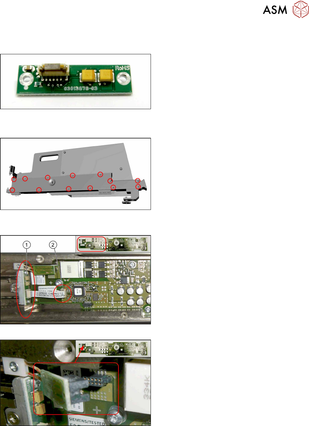
Fig.443: EDIF
●
FBG/EDIF secondary IrDA board
[03013678-xx]
Removal
Fig.444: Removing the cover
► Remove all cross-head screws marked in the pic-
ture.
► Remove the cover from the SIPLACE JTF-ML
Adapter.
Now you have access to the control board X adapter [03050293‑xx].
Fig.445: EDIF on control board X adapter
1. EDIF [03013678-xx]
2. Connector X3 for ribbon cable on control board X
adapter
Fig.446: Disconnecting X1
► Disconnect the X1 plug.
14 JEDEC Tray Feeder
14.1 SIPLACE JTF-ML
306 Service Manual SIPLACE TX Series 06/2017
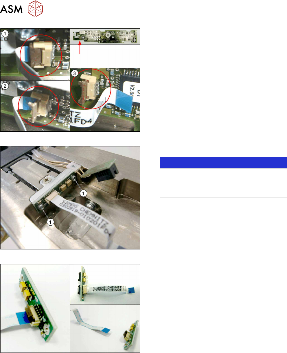
Fig.447: Disconnecting the X3
► Perform steps (1) to(3) to unfold the interlock
and disconnect the X3 plug.
Fig.448: Removing the EDIF
► Remove the two screws(1) fastening the EDIF.
NOTICE!
For a better view the picture shows the EDIF
without control board X adapter.
It is not necessary to remove the control board X
adapter.
.
Fig.449: Disconnecting the flat ribbon cable
► Take out the EDIF off the adapter, together with
the flat ribbon cable.
► Disconnect the flat ribbon cable from the EDIF.
Remember the orientation of the flat ribbon cable.
The unlocking procedure with the interlock is sim-
ilar to the X3 connector above.
14 JEDEC Tray Feeder
14.1 SIPLACE JTF-ML
Service Manual SIPLACE TX Series 06/2017 307
Installation
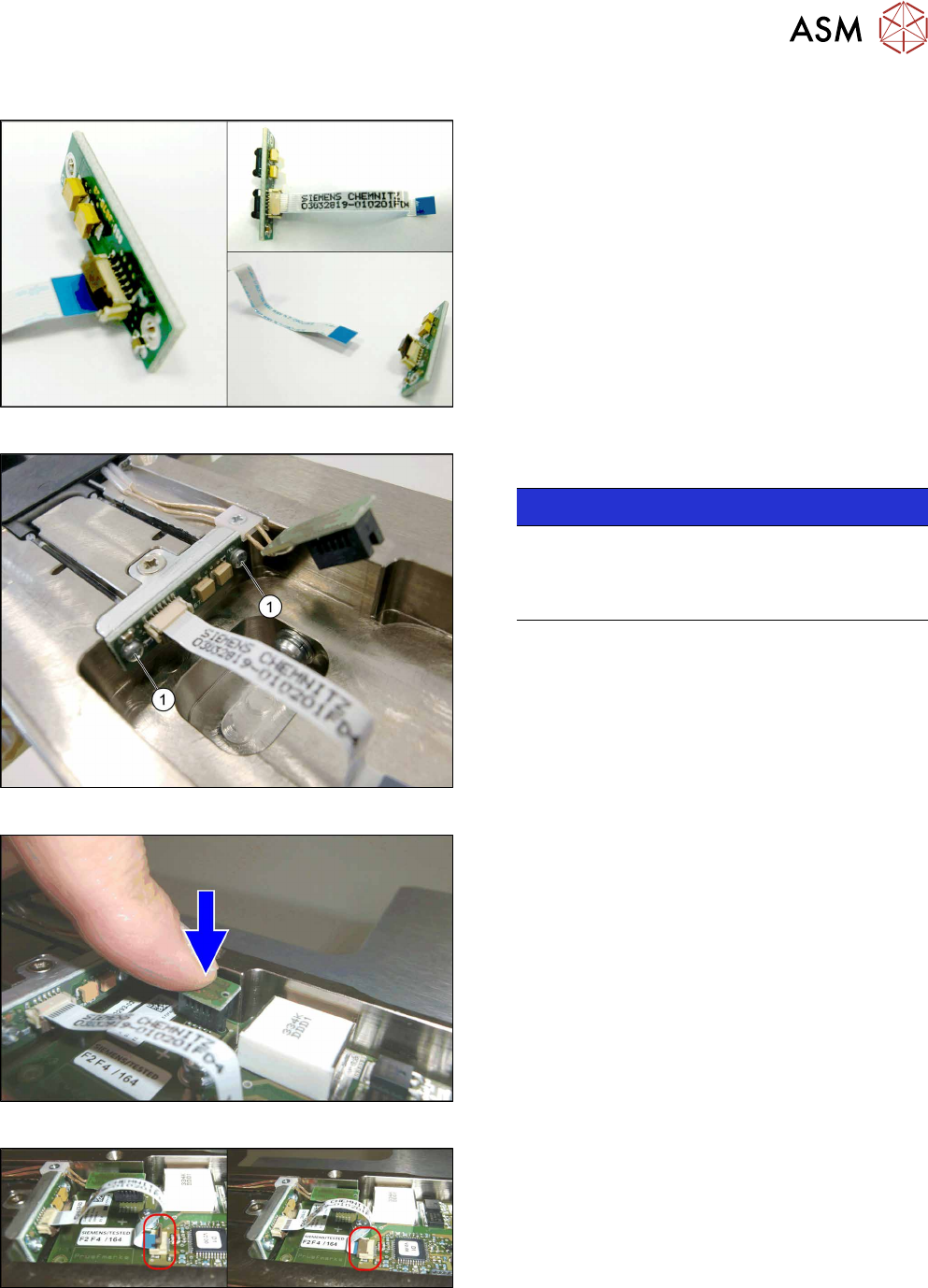
Fig.450: Connecting the flat ribbon cable
► Connect the flat ribbon cable to the new EDIF. Be
aware of the correct orientation of the flat ribbon
cable.
Verify that the cable is fully slipped in the con-
nector base and the ribbon cable is parallel to the
connector base.
Close the interlock by folding it back, similar to
connector X3.
Fig.451: Fitting the EDIF
► Fasten the EDIF with two screws(1).
NOTICE!
For a better view, the diagram shows the EDIF
without the control board X adapter.
It is not necessary to remove the control board X
adapter.
.
Fig.452: Connecting X1
► Connect X1.
Fig.453: Connecting the X3
► Connect X3:
Mount the flat ribbon cable into the X3 base.
Check that the connector is fully slipped in the X3
base and the cable runs parallel to the X3 base.
Close the interlock by folding it back.
► Check the correct connector locking by pulling
the flat ribbon cable gently.