00198150-02_SM_TX_en.pdf - 第34页
3 SMPS 3.1 SMPS - Overview 34 Service Manual SIPLACE TX Series 06/2017 3.1 SMPS - Overview Fig.22: Overview of the SMPS 1. The SMPS is located behind the right cover at location2. 2. Service socket 3. Main power switch…
3 SMPS
2.5 Replacing the Machine Feet [03120976-xx]
Service Manual SIPLACE TX Series 06/2017 33
3 SMPS
DANGER
Observe User Manual
► Please observe the safety instructions in the user manual for all work!
DANGER
Checking for absence of voltage!
► Before you start working, check the power supply for absence of voltage and observe
the waiting times!
NOTICE
Observe the detailed circuit diagrams!
For more detailed information refer to the circuit diagrams folder of your machine.
●
Detailed circuit diagrams folder for SIPLACE TX-Series (up to no. 499) [DE+EN: 00197933-xx]
●
Detailed circuit diagrams folder for SIPLACE TX-Series (from no. 500) [DE+EN: 00198274-xx]
3 SMPS
3.1 SMPS - Overview
34 Service Manual SIPLACE TX Series 06/2017
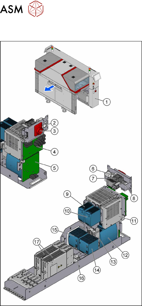
3.1 SMPS - Overview
Fig.22: Overview of the SMPS
1. The SMPS is located behind the right cover at
location2.
2. Service socket
3. Main power switch [03125553‑xx]
4. Fuse and distributor PCB (FD.A1) [03121508‑xx]
3.9 "Replacing the Distribution and Fusing
Assembly" [}55]
5. Distributor assembly TX (I/O control unit)
[03121427‑xx]
3.10 "Replacing the Distributor Assembly
[03121427‑xx]" [}57]
6. Circuit breaker 5SY4 1-POLE 10A C
[03098363‑xx]
7. Power supply 24V/1.3A pulse ML30.241
[03112748‑xx]
3.11 "Replacing the Interior Illumination Power
Supply [03112748-xx]" [}59]
8. K1, Protective contactor combination
[03114295‑xx]
9. AC/DC-Converter DC24V/20A 3-PHASE
[03055232‑xx]
3.8 "Replacing the AC/DC Converter" [}53]
10. AC/DC-Converter DC24V/20A 3-PHASE
[03055232‑xx]
3.8 "Replacing the AC/DC Converter" [}53]
11. Contactor safety breaker (CSB) SMPS
[03112066Sxx]
3.6 "Replacing the CSB (Contactor Safety
Breaker) or the CSB Cover" [}49]
12. Buffer module PCS417.381(CAP) [03103081‑xx]
3.7 "Replacing the Capacitor Battery Buffer Mod-
ule [03103081-xx]" [}52]
13. CAN interface CINX [03108598-xx]
3.12 "Replacing the CAN Interface CINX
[03108598‑xx]" [}61]
14. Pulse unit 4-fold TX (42VDC) [03123989‑xx]
3.8 "Replacing the AC/DC Converter" [}53]
15. AC/DC-Converter DC300/150V 1.3KW 3-PHASE
[03103087‑xx]
3.8 "Replacing the AC/DC Converter" [}53]
16. Measuring points for absence of voltage 2x300 V
DC and ground
3.4 "Checking For Absence of Voltage" [}37]
17. Position controller gantry axes MGCU-2
[03117531Sxx]
3.5 "MGCUs" [}43]
3 SMPS
3.2 Pulling out the Power Supply
Service Manual SIPLACE TX Series 06/2017 35
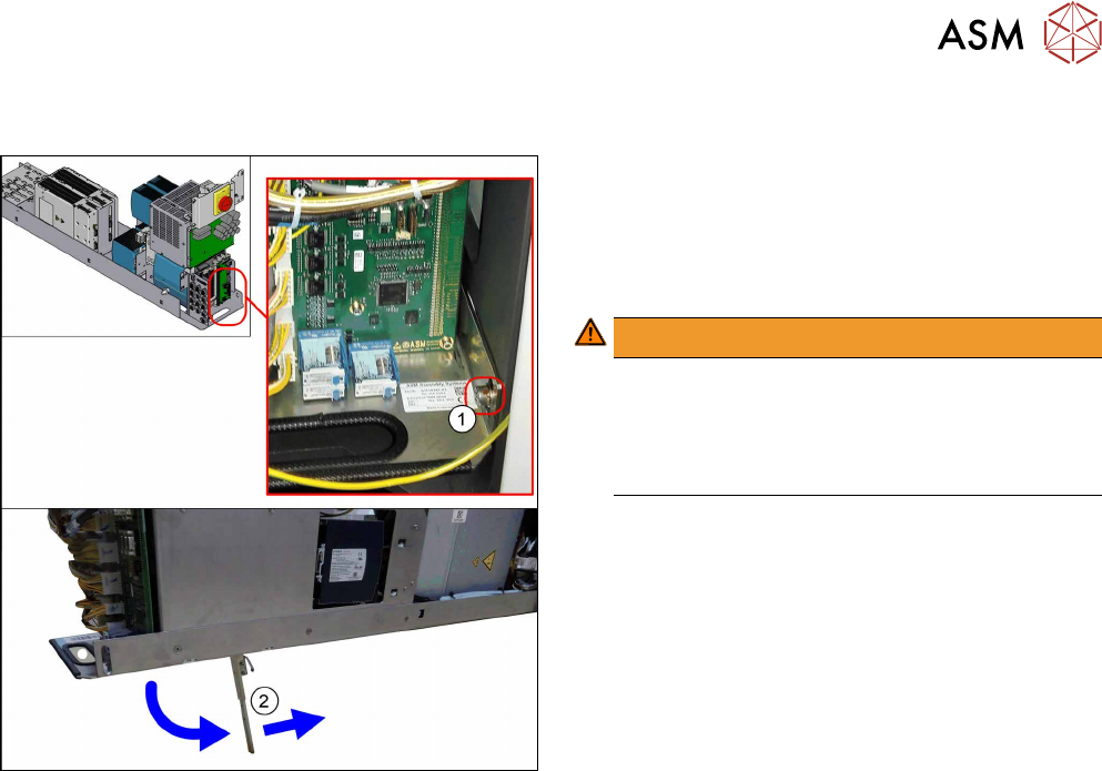
3.2 Pulling out the Power Supply
Fig.23: Leg support
For some service tasks it is necessary to pull the
power supply out of the machine.
► Remove the screw (1) fastening the power sup-
ply.
► Pull the power supply out as far as necessary.
WARNING!
The power supply could fall down without the leg
support(2).
For secure positioning, make sure that the bot-
tom of the leg support points towards the
machine.
.