00198150-02_SM_TX_en.pdf - 第51页
3 SMPS 3.6 Replacing the CSB (Contactor Safety Breaker) or the CSB Cover Service Manual SIPLACE TX Series 06/2017 51 Fig.47: Unplugging the electrical connections underneath ► Unplug the electrical connections between t…
3 SMPS
3.6 Replacing the CSB (Contactor Safety Breaker) or the CSB Cover
50 Service Manual SIPLACE TX Series 06/2017
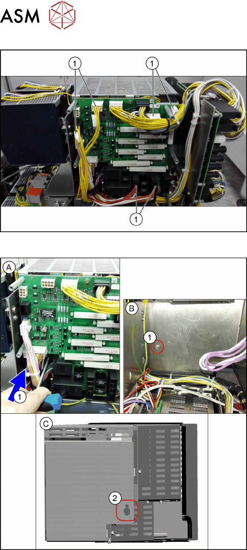
Fig.45: Unplugging the electrical connections at the front
► Unplug the electrical connections(1). You might
like to mark their positions to make clear assign-
ment easier later on.
Fig.46: Removing the CSB
► (A) Loosen the screw(1) on the rear of the CSB.
To access the screw, insert an extension past the
side of the CSB.
Figure (B) shows the power supply without the
CSB for a better view of the screw.
► (C) Unhook the CSB (keyhole (2) on the back of
the CSB).
Lift the CSB until you can reach the connector on
the underside.
3 SMPS
3.6 Replacing the CSB (Contactor Safety Breaker) or the CSB Cover
Service Manual SIPLACE TX Series 06/2017 51
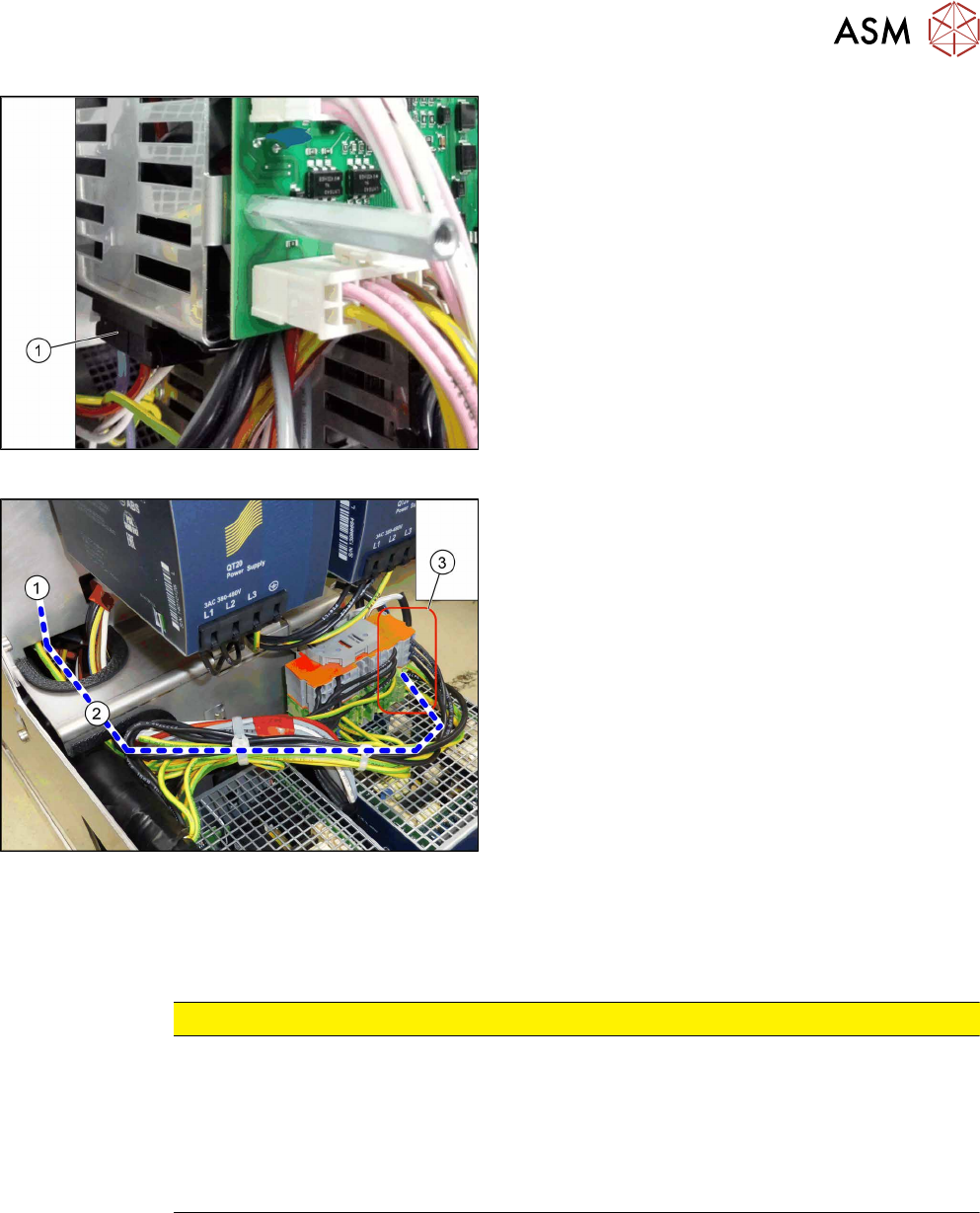
Fig.47: Unplugging the electrical connections underneath
► Unplug the electrical connections between the
CSB and the capacitor battery(1) (on the under-
side of the CSB).
► Carefully lift off the CSB.
The CSB is still connected to the SMPS by the
grounding cable.
Fig.48: Cables
► Disconnect the yellow-green cable(2) from the
connection field(3) and carefully remove the
CSB(1). You may want to mark the position to
make clear assignment easier later on.
Remove cable ties where necessary.
Installation
► Follow the removal instructions in reverse order for installation. Also observe the following in-
structions:
CAUTION
Installation instructions
► Make sure that the cables are run correctly.
► The cables must not be pinched or rub against unprotected edges.
► Make sure that the cables are only run out of the CSB through the two re-
cessesprovided.
► Replace any cables ties where needed.
3 SMPS
3.7 Replacing the Capacitor Battery Buffer Module [03103081-xx]
52 Service Manual SIPLACE TX Series 06/2017
3.7 Replacing the Capacitor Battery Buffer Module
[03103081-xx]
Parts, equipment and tools
●
Capacitor battery PCS417.381 (CAP) [03103081-xx]
Overview
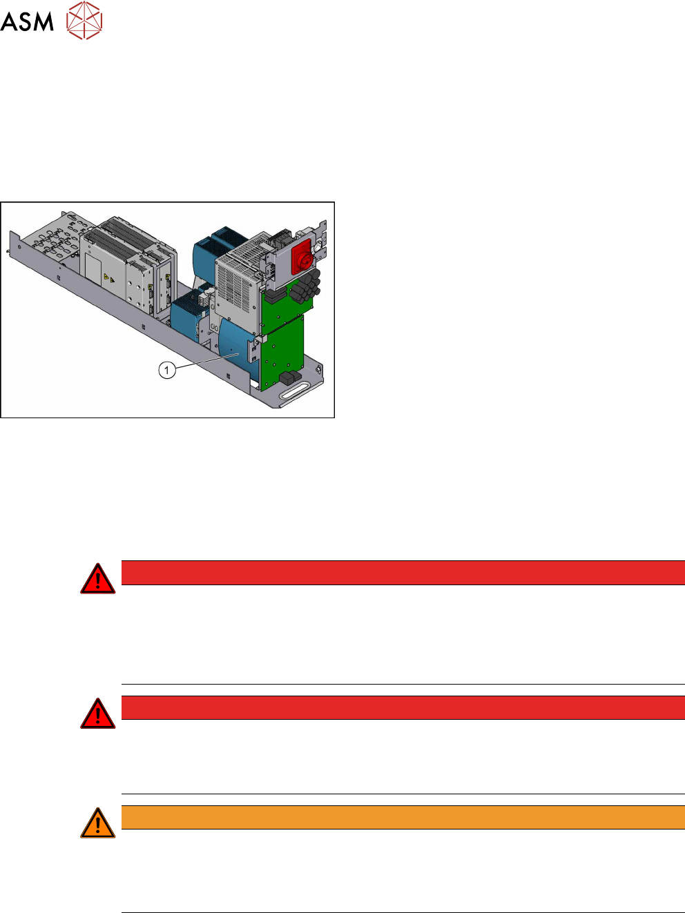
Fig.49: Capacitor battery
1. Capacitor battery
Removal
► Switch off the machine, disconnect it from the power supply and secure it to prevent
unauthorized reactivation. Observe the instructions in section 1.2 "Preparatory Work..." [}15].
► Remove the power supply fastening screw and pull out the power supply. For more informa-
tion about this read section 3.2 "Pulling out the Power Supply" [}35].
DANGER
High voltages
High DC voltages can be present in the capacitor battery.
► Observe the waiting period after power supply switch-off (5 minutes).
► Observe the LED display on the capacitor battery. This will show any residual voltages
still present.
DANGER
Checking for absence of voltage!
► Before you start working check the power supply for absence of voltage and observe
the waiting times! For more information about this read section 3.4 "Checking For Ab-
sence of Voltage" [}37].
WARNING
Carefully pull out the power supply
The power supply is not permanently fixed and can fall out of the machine.
► Pull the power supply out of the machine but not too far.
► If necessary, use suitable support e. g. a wooden beam.
► Remove contactor safety breaker. For more information about this, read section 3.6 "Repla-
cing the CSB (Contactor Safety Breaker) or the CSB Cover" [}49].