00198150-02_SM_TX_en.pdf - 第72页
4 Electrical System and Control 4.7 Indicator Lamps and Illumination 72 Service Manual SIPLACE TX Series 06/2017 4.7 Indicator Lamps and Illumination 4.7.1 Replacing the Indicator Lamp Parts, equipment and tools ● When r…
4 Electrical System and Control
4.6 Replacing the Cover Switch [03110691-xx]
Service Manual SIPLACE TX Series 06/2017 71
Removal with removing the side cover
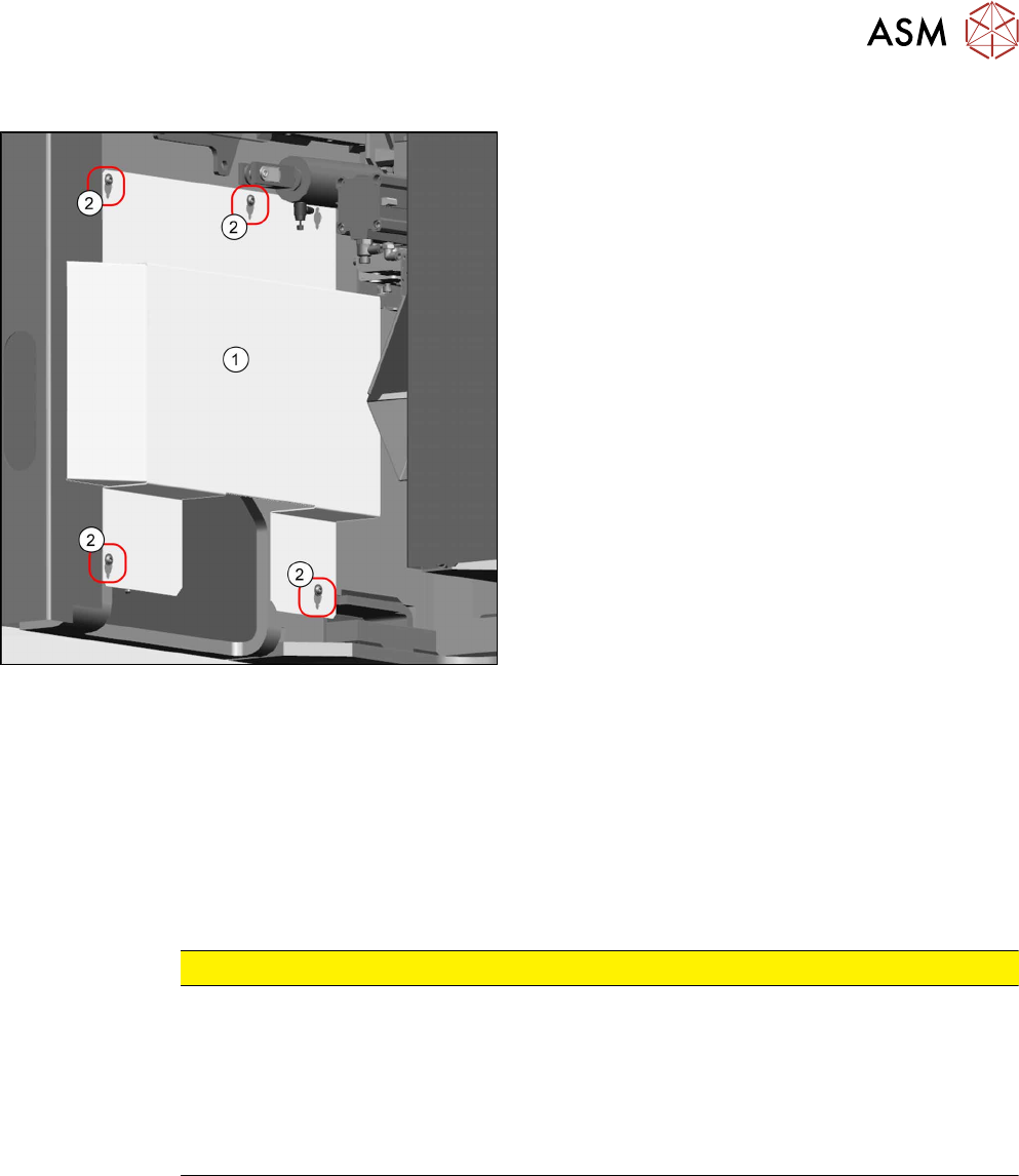
Fig.76: Lower side cover
► Loosen the screws(2) fastening the side
cover(1) and remove the side cover.
► Remove the screws fastening the cover switch.
ð Now you have access to the connector.
► Disconnect the cable.
► Carefully pull the cable until the connector comes out of the side cover, at the top.
Installation
► Follow the removal instructions in reverse order for installation. Also observe the following in-
structions:
CAUTION
Installation instructions
► The cover switch must be set to the cover. Make sure that the cover switch is clean
and switches properly. The cover switch needs to be set so that even a minimal open-
ing of the cover will trigger the safety circuit.
Also read section 2.4.1 "Setting the Covers" [}30].
► Switch the machine on and make sure that the cover switch activates the safety cir-
cuit, when the covers are opened.
4 Electrical System and Control
4.7 Indicator Lamps and Illumination
72 Service Manual SIPLACE TX Series 06/2017
4.7 Indicator Lamps and Illumination
4.7.1 Replacing the Indicator Lamp
Parts, equipment and tools
●
When replacing the indicator lamp:
– Tower light standard [03103121-xx]
NOTICE
Two- and three-part fault indicator lamp
The fault indicator lamp consists of a green basic module and can be configured as a two-
part version or a three-part version:
► Light tower, two colors [00519895Sxx] (with an additional white continuous light ele-
ment)
► Light tower, three colors [00519896Sxx] (with an additional red and yellow continuous
light element)
●
When replacing the light elements in the indicator lamp:
– LED module tower light green LU5-E-G [03103116‑xx]
– LED module tower light red LU5-E-R [03103117‑xx]
– LED module tower light yellow LU5-E-Y [03103118‑xx]
Overview
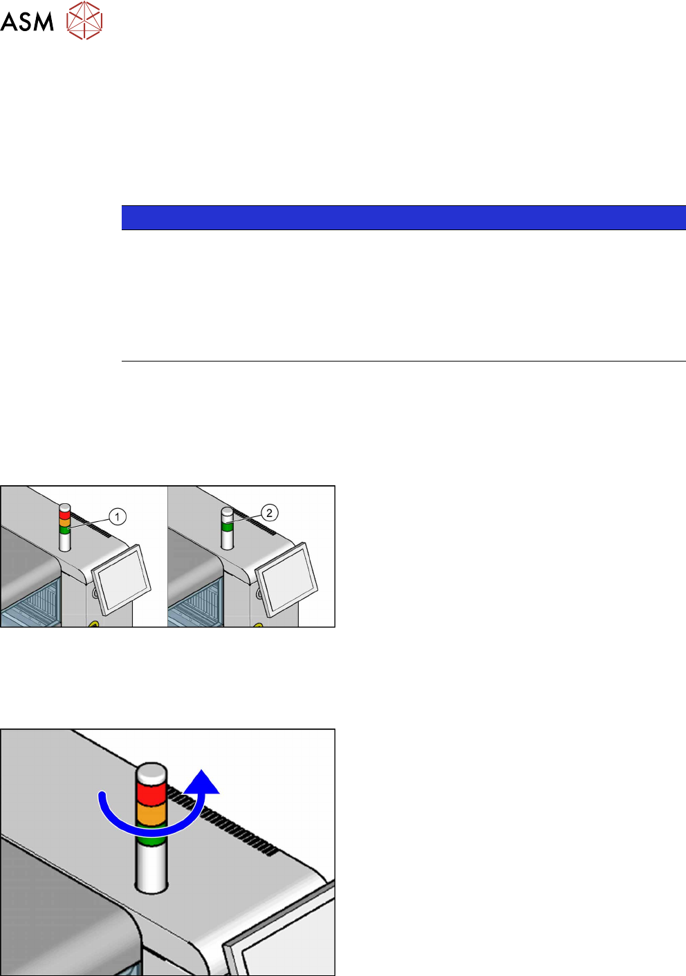
Fig.77: Three color indicator lamp
1. Three color indicator lamp (red/yellow/green)
2. Two color indicator lamp (white/green)
Removal
► Switch off the machine, disconnect it from the power supply and secure it to prevent
unauthorized reactivation. Observe the instructions in section 1.2 "Preparatory Work..." [}15].
Fig.78: Removing the indicator lamp
► Turn the housing of the indicator lamp anticlock-
wise, to loosen it.
► Take the housing of the indicator lamp up and off.
4 Electrical System and Control
4.7 Indicator Lamps and Illumination
Service Manual SIPLACE TX Series 06/2017 73
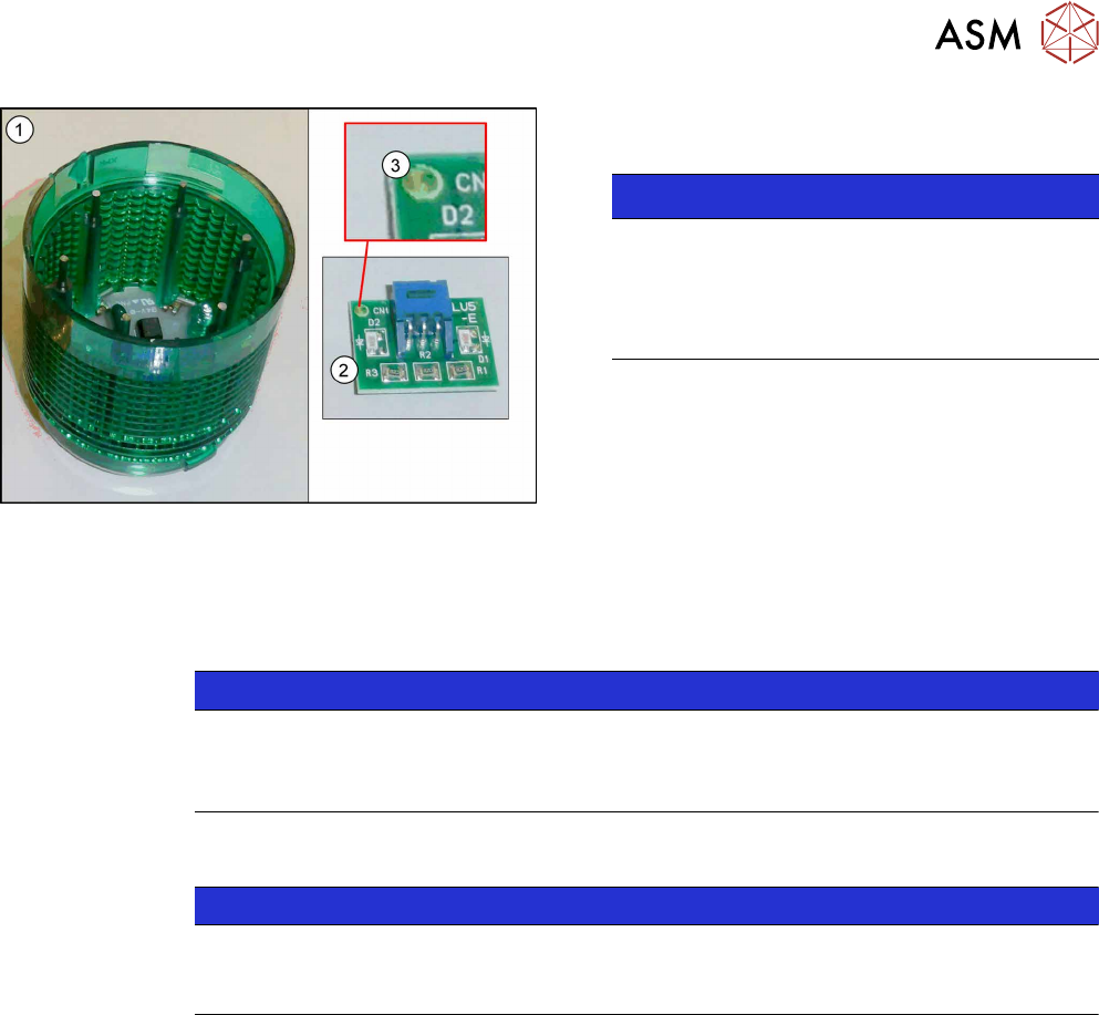
Fig.79: LED module with housing
► Remove the LED module(2) from the indicator
lamp housing(1).
NOTICE!
The dot(3) in the corner of the LED module in-
dicates the color of the LED.
The dot must correspond to the housing color.
There are white, green, yellow and red LED
modules.
.
Installation
► Installation is performed by following the above instructions in the reverse order. Observe the
following instructions:
NOTICE
Installation instructions
► Make sure that the LED module and the housing have the same color.
► Check the function of the indicator lamp.
4.7.2 Conversion 2-/3-Part Indicator Lamp
NOTICE
Description example
The following section describes the conversion of a two-part lamp into a three-part lamp.
The conversion of a three-part lamp into a two-part lamp is identical.
Parts, Equipment and Tools
●
For converting a two-part lamp into a three-part one:
Light tower three colors [00519896Sxx]
●
For converting a three-part lamp into a two-part one:
Light tower two colors [00519895Sx]
Procedure
► Switch off the machine, disconnect it from the power supply and secure it to prevent
unauthorized reactivation. Observe the instructions in section 1.2 "Preparatory Work..." [}15].
You can individually lift off each color segment (= base unit) of the indicator lamp.
► Lift off the white color segment with a short rotation.
► Insert the new color segments and new light elements, if necessary.
When inserting the light elements, observe the identification on the casing.
► Attach the yellow and the green color segment with a short rotation.
► Check the function of the indicator lamp.