00198150-02_SM_TX_en.pdf - 第74页
4 Electrical System and Control 4.8 Replacing the Cover Fan [03110692-xx] 74 Service Manual SIPLACE TX Series 06/2017 4.8 Replacing the Cover Fan [03110692-xx] Parts, equipment and tools ● Fan, monitored [03110692-xx] or…
4 Electrical System and Control
4.7 Indicator Lamps and Illumination
Service Manual SIPLACE TX Series 06/2017 73
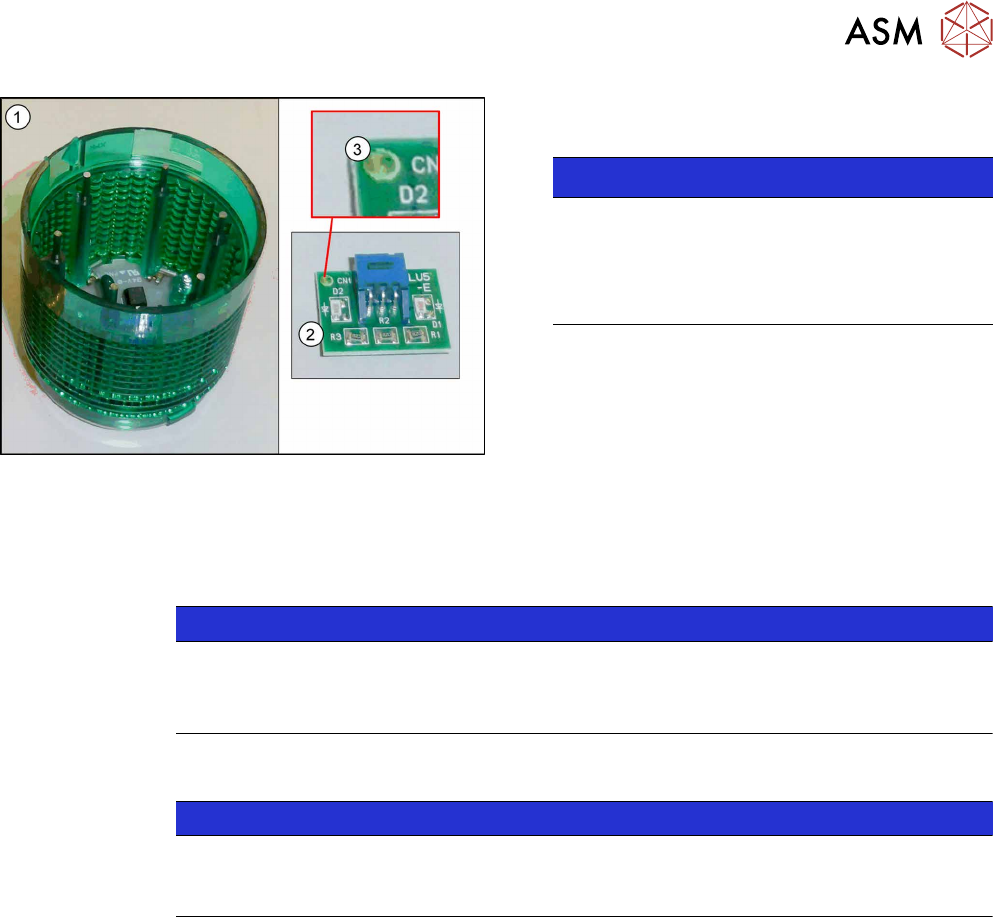
Fig.79: LED module with housing
► Remove the LED module(2) from the indicator
lamp housing(1).
NOTICE!
The dot(3) in the corner of the LED module in-
dicates the color of the LED.
The dot must correspond to the housing color.
There are white, green, yellow and red LED
modules.
.
Installation
► Installation is performed by following the above instructions in the reverse order. Observe the
following instructions:
NOTICE
Installation instructions
► Make sure that the LED module and the housing have the same color.
► Check the function of the indicator lamp.
4.7.2 Conversion 2-/3-Part Indicator Lamp
NOTICE
Description example
The following section describes the conversion of a two-part lamp into a three-part lamp.
The conversion of a three-part lamp into a two-part lamp is identical.
Parts, Equipment and Tools
●
For converting a two-part lamp into a three-part one:
Light tower three colors [00519896Sxx]
●
For converting a three-part lamp into a two-part one:
Light tower two colors [00519895Sx]
Procedure
► Switch off the machine, disconnect it from the power supply and secure it to prevent
unauthorized reactivation. Observe the instructions in section 1.2 "Preparatory Work..." [}15].
You can individually lift off each color segment (= base unit) of the indicator lamp.
► Lift off the white color segment with a short rotation.
► Insert the new color segments and new light elements, if necessary.
When inserting the light elements, observe the identification on the casing.
► Attach the yellow and the green color segment with a short rotation.
► Check the function of the indicator lamp.
4 Electrical System and Control
4.8 Replacing the Cover Fan [03110692-xx]
74 Service Manual SIPLACE TX Series 06/2017
4.8 Replacing the Cover Fan [03110692-xx]
Parts, equipment and tools
●
Fan, monitored [03110692-xx] or
Cover fan 1 part [03052317-xx]
●
Loctite 241 [02101037‑xx]
Overview
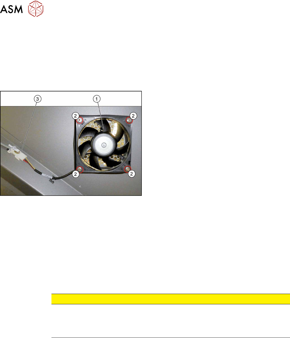
Fig.80: Cover fan
1. Cover fan
2. Fastening screws for cover fan
3. Connection cable for cover fan
Removal
► Switch off the machine, disconnect it from the power supply and secure it to prevent
unauthorized reactivation. Observe the instructions in section 1.2 "Preparatory Work..." [}15].
► Remove the four screws fastening the cover fan. Make sure that the washers are not lost. You
may want to mark the direction of fan operation, to make clear assignment easier later on.
► Unplug the cover fan connection cable and remove the cover fan from the machine.
Installation
► Follow the removal instructions in reverse order for installation. Also observe the following in-
structions:
CAUTION
Installation instructions
► When fitting the fan, note the correct direction of air flow. All fans blow the air out of
the machine.
► Secure the four fastening screws with Loctite 241.
5 Pneumatic System
5.1 Pneumatic System – Overview
Service Manual SIPLACE TX Series 06/2017 75
5 Pneumatic System
DANGER
Observe User Manual
► Please observe the safety instructions in the user manual for all work!
CAUTION
Switch off the compressed air supply.
When working on the pneumatic system, always disconnect the machine from the com-
pressed air supply.
CAUTION
Use the correct blanking plugs
► Only use blanking plugs in the machine which match the manufacturer's compressed
air connection. A tight fit cannot be guaranteed for other blanking plugs.
► We recommend the use of blanking plugs made by Festo.
5.1 Pneumatic System – Overview
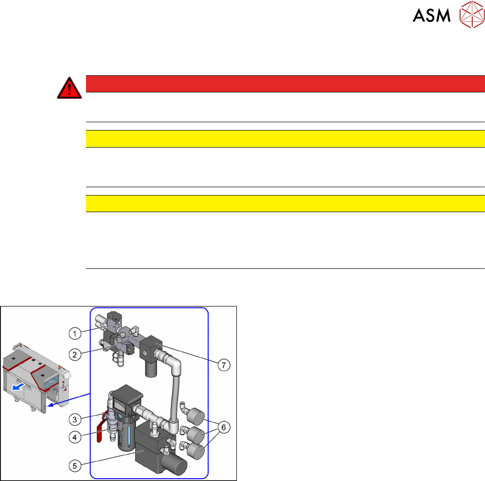
Fig.81: Pneumatics
The pneumatic system is located at location 2, behind
the side cover.
1. Solenoid valve 5/2 G1/4 without manual actuator
[00344974Sxx]
Safety valve(V2) for tape cutter
2. 5/2 way valve G1/8 DN 4mm [03062277‑xx]
Main valve (V1) for NC, inset
3. Main switch valve [03065266‑xx]
4. Filter, G1/2 inch, modular 112, 5æm
[03028258‑xx]
5. Sentronic-D DN8 SUBB1/4 10bar
[03065425Sxx]
Proportional controller for gantry group place-
ment heads
5.5 "Replacing the Proportional Controller (Loca-
tion 2) [03065425-xx]" [}79]
6. Pressure gauge D40, G1/8, 0-10bar
[03040678‑xx]
For machine, gantry and inlet pressure
7. Pressure regulator G1/4 (34204034)
[03065185-xx]
5.3 "Setting the Compressed Air Controller for
Machine Components" [}76]
5.4 "Replacing the Pressure Regulator
[03065185-xx]" [}76]