00198150-02_SM_TX_en.pdf - 第76页
5 Pneumatic System 5.2 Sealing the Pneumatic Screwed Connections 76 Service Manual SIPLACE TX Series 06/2017 5.2 Sealing the Pneumatic Screwed Connections NOTICE Sealing the pneumatic screwed connections If pneumatic scr…
5 Pneumatic System
5.1 Pneumatic System – Overview
Service Manual SIPLACE TX Series 06/2017 75
5 Pneumatic System
DANGER
Observe User Manual
► Please observe the safety instructions in the user manual for all work!
CAUTION
Switch off the compressed air supply.
When working on the pneumatic system, always disconnect the machine from the com-
pressed air supply.
CAUTION
Use the correct blanking plugs
► Only use blanking plugs in the machine which match the manufacturer's compressed
air connection. A tight fit cannot be guaranteed for other blanking plugs.
► We recommend the use of blanking plugs made by Festo.
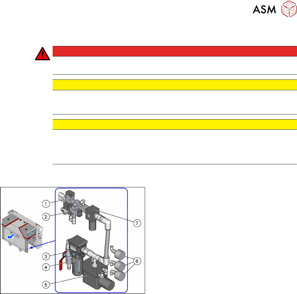
5.1 Pneumatic System – Overview
Fig.81: Pneumatics
The pneumatic system is located at location 2, behind
the side cover.
1. Solenoid valve 5/2 G1/4 without manual actuator
[00344974Sxx]
Safety valve(V2) for tape cutter
2. 5/2 way valve G1/8 DN 4mm [03062277‑xx]
Main valve (V1) for NC, inset
3. Main switch valve [03065266‑xx]
4. Filter, G1/2 inch, modular 112, 5æm
[03028258‑xx]
5. Sentronic-D DN8 SUBB1/4 10bar
[03065425Sxx]
Proportional controller for gantry group place-
ment heads
5.5 "Replacing the Proportional Controller (Loca-
tion 2) [03065425-xx]" [}79]
6. Pressure gauge D40, G1/8, 0-10bar
[03040678‑xx]
For machine, gantry and inlet pressure
7. Pressure regulator G1/4 (34204034)
[03065185-xx]
5.3 "Setting the Compressed Air Controller for
Machine Components" [}76]
5.4 "Replacing the Pressure Regulator
[03065185-xx]" [}76]
5 Pneumatic System
5.2 Sealing the Pneumatic Screwed Connections
76 Service Manual SIPLACE TX Series 06/2017
5.2 Sealing the Pneumatic Screwed Connections
NOTICE
Sealing the pneumatic screwed connections
If pneumatic screwed connections are loosened, these will need to be sealed again after-
wards. Always use the same sealing technique as was used before they were removed.
The following sealing techniques are available:
► Sealing ring (rubber or plastic)
These are either supplied or you can use the ones used before. Check the condition of
used sealing rings for damage.
► Sealant
There are several variants of this:
Loctite 567 [03097172-xx] and Loctite 55 [03092492-xx]
After loosening the pneumatic screwed connection, clean the screwed thread and seal
it with Loctite. The sealing thread for Loctite 55 must be wound on in the direction of
the screwed thread.
There may also already be a sealant on the screwed thread.
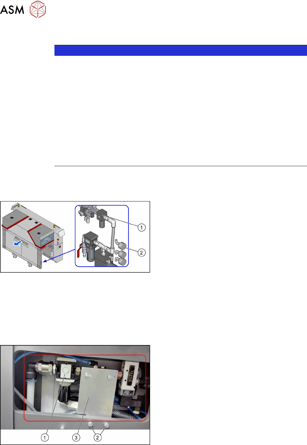
5.3 Setting the Compressed Air Controller for Machine
Components
► Make sure that the compressed air controller(1)
for machine components is set to 5.1bar(2).
5.4 Replacing the Pressure Regulator [03065185-xx]
Parts, equipment and tools
●
Pressure regulator G1/4 (34204034) [03065185-xx]
●
Sealant (see 5.2 "Sealing the Pneumatic Screwed Connections" [}76])
Overview
Fig.82: Pressure regulator in machine
1. Pressure regulator
2. Two fastening screws for the holder
3. Holder
5 Pneumatic System
5.4 Replacing the Pressure Regulator [03065185-xx]
Service Manual SIPLACE TX Series 06/2017 77
Removal
► Switch off the machine, disconnect it from the power supply and secure it to prevent
unauthorized reactivation. Observe the instructions in section 1.2 "Preparatory Work..." [}15].
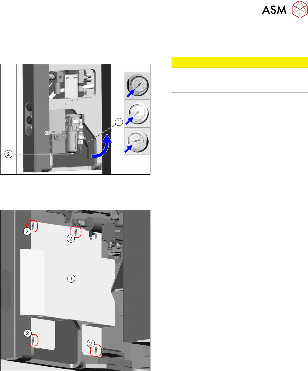
Fig.83: Disabling the compressed air supply
CAUTION!
Switch off the compressed air supply.
When working on the pneumatic system, always
switch off the compressed air supply.
.
► Push the lever (1) for the compressed air supply
back, until it is positioned horizontally.
► Open the screw (2) on the inlet filter to vent the
system. Hold a cloth underneath to capture any
escaping oil.
► All pressure gauges must be set to zero.
► Disconnect the machine from the compressed air
supply.
Fig.84: Lower side cover
► Loosen the screws(2) fastening the side
cover(1) at location 2 and remove the side cover.