00198150-02_SM_TX_en.pdf - 第84页
6 Gantries 6.2 X and Y Axis 84 Service Manual SIPLACE TX Series 06/2017 6.2 X and Y Axis 6.2.1 Gantries - X and Y Axis - Overview Fig.93: Gantry 1. X axis incremental encoder and mounting bracket 6.2.2 "Replacing t…
6 Gantries
6.1 Gantries - Overview
Service Manual SIPLACE TX Series 06/2017 83
6 Gantries
DANGER
Observe User Manual
► Please observe the safety instructions in the user manual for all work!
CAUTION
Use the correct blanking plugs
► Only use blanking plugs in the machine which match the manufacturer's compressed
air connection. A tight fit cannot be guaranteed for other blanking plugs.
► We recommend the use of blanking plugs made by Festo.
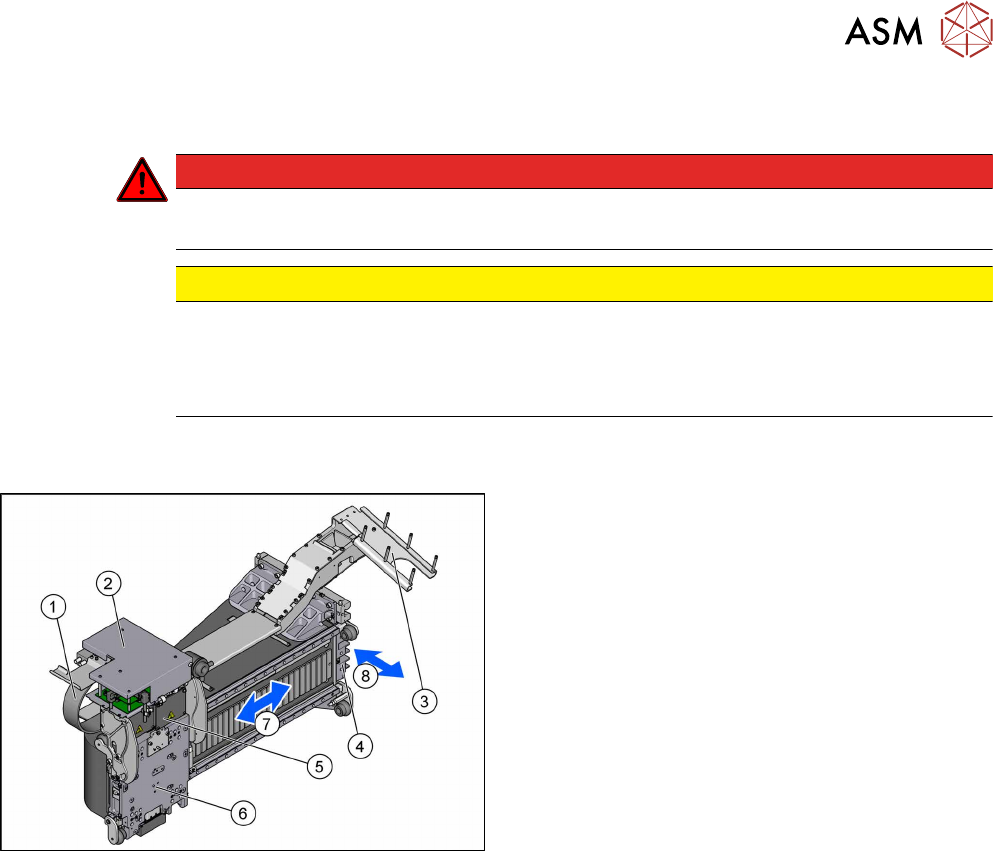
6.1 Gantries - Overview
Fig.92: Gantry
1. Gantry trailing cables split for X axis
6.3 "Trailing Cable and Printed Circuit
Boards" [}96]
2. Head boards complete (under the cover)
6.4 "MHCU, Boards and Camera" [}113]
3. Y axis trailing cable
6.3 "Trailing Cable and Printed Circuit
Boards" [}96]
4. Y drive (primary)
5. MHCU
6.4 "MHCU, Boards and Camera" [}113]
6. Head plate with X drive/primary drive
7. X axis
6.2 "X and Y Axis" [}84]
8. Y-Axis
6.2 "X and Y Axis" [}84]
6 Gantries
6.2 X and Y Axis
84 Service Manual SIPLACE TX Series 06/2017
6.2 X and Y Axis
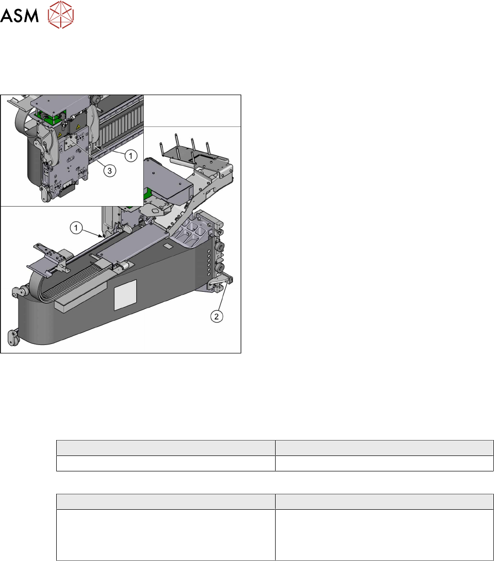
6.2.1 Gantries - X and Y Axis - Overview
Fig.93: Gantry
1. X axis incremental encoder and mounting bracket
6.2.2 "Replacing the X Axis Incremental Encoder/
Mounting Bracket [03094995‑xx]" [}84]
2. Y axis incremental encoder and mounting bracket
6.2.3 "Replacing the Y Axis Incremental Encoder/
Mounting Bracket [03094996‑xx]" [}87]
3. attachment head suspension
6.2.9 "Replacing Attachment Head Suspension
[03124850-xx]" [}93]
●
6.2.5 "Track Signals and Zero Pulse" [}89]
●
6.2.6 "Replacing the Y Axis Buffer (SIPLACE Ser-
vice only)" [}92]
●
6.2.7 "Replacing the X Scale (SIPLACE Service
only)" [}92]
●
6.2.8 "Replacing the Y Scale (SIPLACE Service
only)" [}92]
●
6.2.10 "Installation Check for X Motor
Plate" [}94]
6.2.2 Replacing the X Axis Incremental Encoder/Mounting Bracket [03094995‑xx]
Parts, equipment and tools
●
Select the correct incremental encoder:
SIPLACE TX1/TX2/TX2i SIPLACE TX2 micron / TX2i micron
Read head MS 22.84 X axis [03094995-xx] Read head [03146505‑xx]
●
If necessary: select the right holder for the incremental encoder:
SIPLACE TX1/TX2/TX2i SIPLACE TX2 micron / TX2i micron
X read head mounting bracket RSF MS 20
[03089506‑xx]
Gantry 1: Mounting bracket X RSF MS 30.03
BK Robax G1 [03132145‑xx]
Gantry 2: Mounting bracket X RSF MS 30.03
BK Robax [03103206‑xx]
●
Test device PG1-I (MS22/MS30) assembly [03102699-xx]
●
Loctite 241 [02101037‑xx]
●
Ethanol
Isopropanol – IPA can be used as an alternative.
●
Plastic feeler gauge 0.75mm [03090774-xx]
●
Stepladder, if required
6 Gantries
6.2 X and Y Axis
Service Manual SIPLACE TX Series 06/2017 85
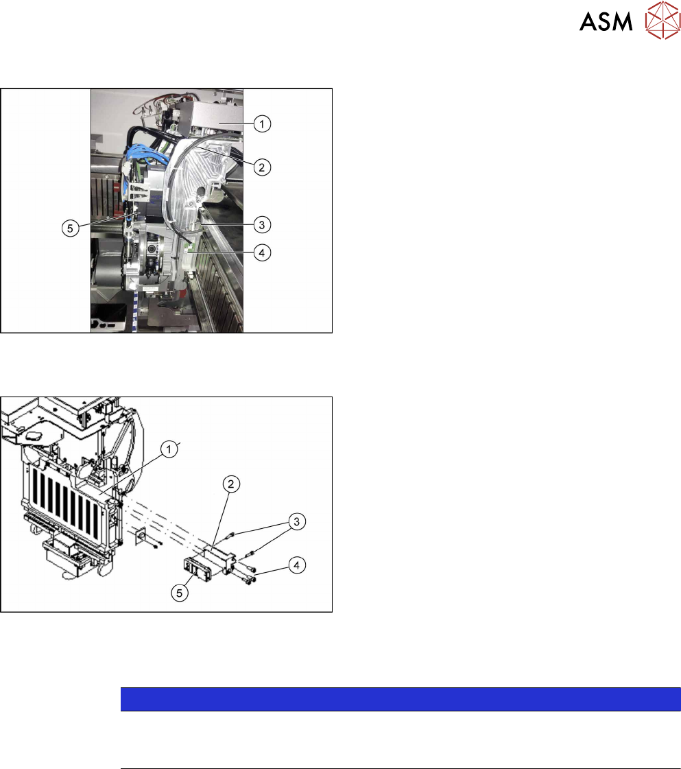
Overview
Fig.94: Incremental encoder overview
1. Head interface and Vision board under the cover
2. Cable from temperature sensor and incremental
encoder X axis to head interface
3. X axis incremental encoder with mounting
bracket
4. Temperature sensor
5. Placement head
Removal
Fig.95: Removing the incremental encoder
1. Head plate - rear view
2. X read head mounting bracket
3. Two fastening screws for read head
4. Three fastening screws for mounting bracket
5. Incremental encoder
► Switch off the machine, disconnect it from the power supply and secure it to prevent
unauthorized reactivation. Observe the instructions in section 1.2 "Preparatory Work..." [}15].
NOTICE
Recommendation
► We recommend that you always perform these tasks from the opposite side, over the
other gantry. You may need to use a stepladder or something similar to help you.
► Unplug the incremental encoder press-fit connection from the head interface. In this case
make a note of the position to make clear assignment easier later on.
► Unthread the connection cable as far as the incremental encoder (2).
► Loosen the three screws (4) fastening the X read head mounting bracket with incremental en-
coder and carefully remove the incremental encoder with the mounting bracket.
► Remove the two screws (3) and then remove the incremental encoder.