00198150-02_SM_TX_en.pdf - 第90页
6 Gantries 6.2 X and Y Axis 90 Service Manual SIPLACE TX Series 06/2017 6.2.5.1 Test Device PG1-I (MS22/MS30) [03102699-xx] – Operation Fig.100: Operating of test device PG1-I - 1

6 Gantries
6.2 X and Y Axis
Service Manual SIPLACE TX Series 06/2017 89
6.2.4 Mechanical Adjustment of the Incremental Encoder
The incremental encoders (read units) on the X and Y axis are adjusted exactly to the position of
the incremental scale. The two limit marks on the incremental encoder show where the top/bottom
positions of the scale should be. They are also mechanically set to a distance of 0.75mm (black-
white scale) to the incremental scale.
NOTICE
Plastic disks
To set this distance, use one or more small plastic disks with a total thickness of 0.75mm.
► Feeler gauge 0.75mm plastic [03090774-xx] (white)
After this adjustment of the incremental encoder you have to check the zero pulse and track sig-
nals.
Correct installation should ensure correct count and zero pulse signals. For troubleshooting pur-
poses (error analysis and fixing) you will need to measure these signals.
Please also observe section 6.2.5 "Track Signals and Zero Pulse" [}89].
6.2.5 Track Signals and Zero Pulse
Check
Proceed as follows to check the zero pulse.
► Switch off the machine.
► Unplug the incremental encoder from the head interface or the gantry interface and connect it
to the test device. (See 6.2.5.1 "Test Device PG1-I (MS22/MS30) [03102699-xx] – Opera-
tion" [}90])
► Move the head or gantry manually back and forth. This movement enables you to read the
correct track signal progress from the test device.
► If the track signal is not within the tolerance range, you will need to reset the incremental en-
coder. The incremental encoder has then been fitted either too near, too far away, inclined
and/or displaced.

6 Gantries
6.2 X and Y Axis
90 Service Manual SIPLACE TX Series 06/2017
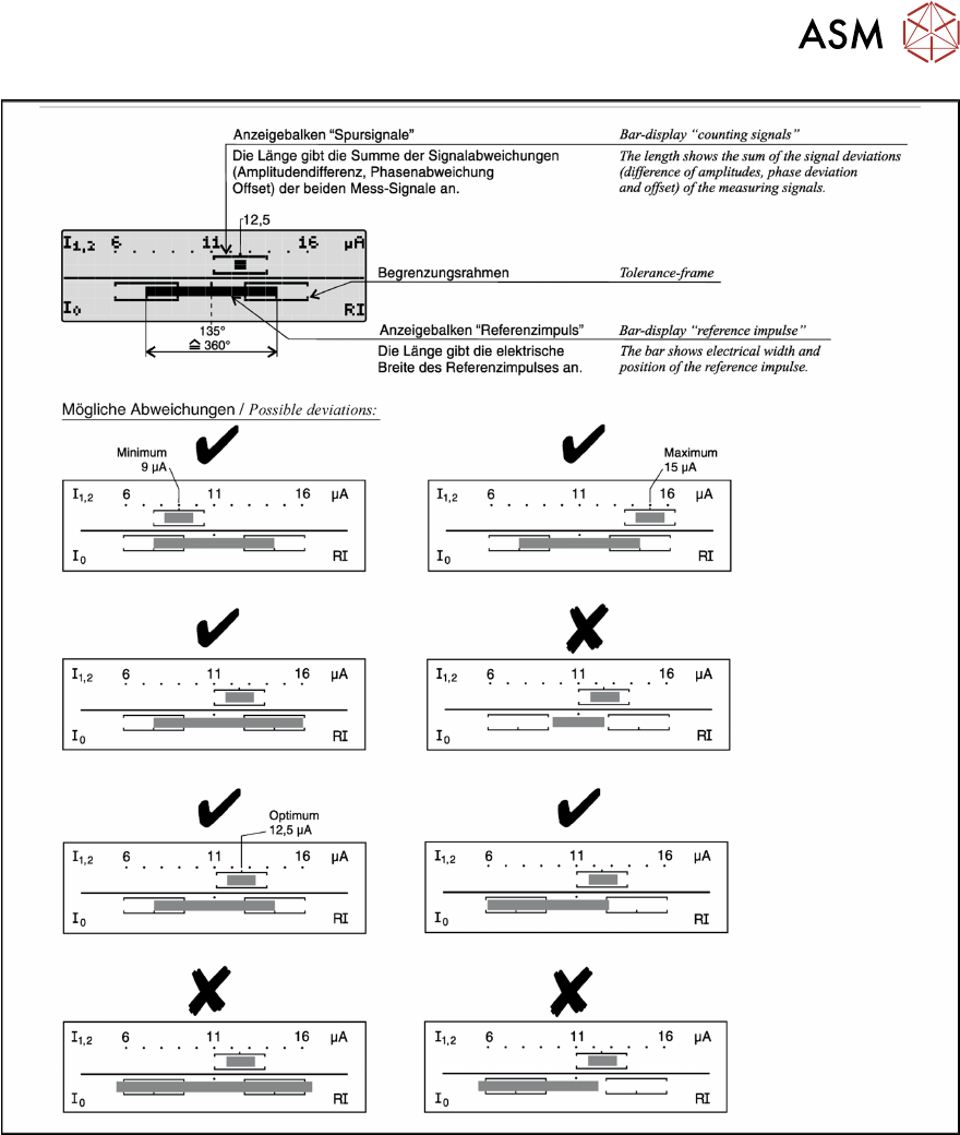
6.2.5.1 Test Device PG1-I (MS22/MS30) [03102699-xx] – Operation
Fig.100: Operating of test device PG1-I - 1
6 Gantries
6.2 X and Y Axis
Service Manual SIPLACE TX Series 06/2017 91
Fig.101: Operating of test device PG1-I - 2