00194598-01.pdf - 第50页
2 Retrofit instructions: ceramic substrate centering for SIPLACE S -27 HM Ceramic substrate centering SIPLACE S -27 HM 12/2004 Edition 50 : Use the too l to lift the comp ression s pring on th e PCB cl amp as far as the …
Ceramic substrate centering SIPLACE S-27 HM 2 Retrofit instructions: ceramic substrate centering for SIPLACE S-27 HM
12/2004 Edition
49
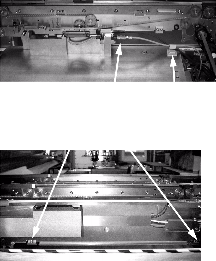
: Connect the compressed air hose to the ceramic substrate centering and connect electrically.
2
2.5.1 Installing the lifting table travel limiter
2
2
2
2
2
2
2
2
Connections
Cable clamp
PCB clamp
2 Retrofit instructions: ceramic substrate centering for SIPLACE S-27 HM Ceramic substrate centering SIPLACE S-27 HM
12/2004 Edition
50
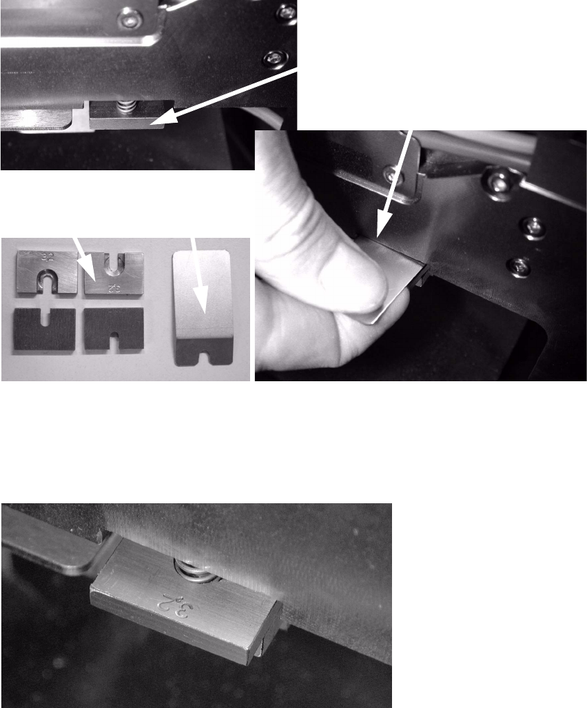
: Use the tool to lift the compression spring on the PCB clamp as far as the stop.
2
2
: Insert the travel limiter. You must feel the compression spring snap into place.
2
: Remove the tool.
: Insert two travel limiters per conveyor side wall and placement area.
2
PCB clamp
Lift the compression spring
Travel limiter
Tools
00366960-02-xx Travel limiter 2.5 mm for SIPLACE HS-60/S-27 HM

Ceramic substrate centering SIPLACE S-27 HM 2 Retrofit instructions: ceramic substrate centering for SIPLACE S-27 HM
12/2004 Edition
51
: If you wish to remove the travel limiters, insert the tool over the limiter and then pull the spring
up.
The travel limiter can then be pulled out at the side.
2
Make sure that the spring does not jump out. It must be lowered correctly back into a groove or
placed around the pins. 2
2
Please contact Siemens L&A Product Management if you need to place the PCBs right up to the
edge. 2
2.6 Set the response distance of the proximity switch
: Make sure that the active surface of the inductive proximity switch is set back 0.2 mm from the
stop surface of the carriage unit in the hole.
This prevents the proximity switch acting as a stop during the opening movement, and thus
being damaged.
: Correct the position of the proximity switch if necessary (grub screw, size 1 hexagon socket
spanner).
The proximity switch has an LED for checking the switching process.