00194598-01.pdf - 第57页
Ceramic substrate centering SIPLACE S- 27 HM 2 Retrofit instructions: ceramic substrate centering for SIPLACE S-27 HM 12/2004 Edition 57 2.9 Circuit diagram 2 Fig. 2.9 - 1 SIPLACE S-27 HM wiring diagram Conversio n board…
2 Retrofit instructions: ceramic substrate centering for SIPLACE S-27 HM Ceramic substrate centering SIPLACE S-27 HM
12/2004 Edition
56
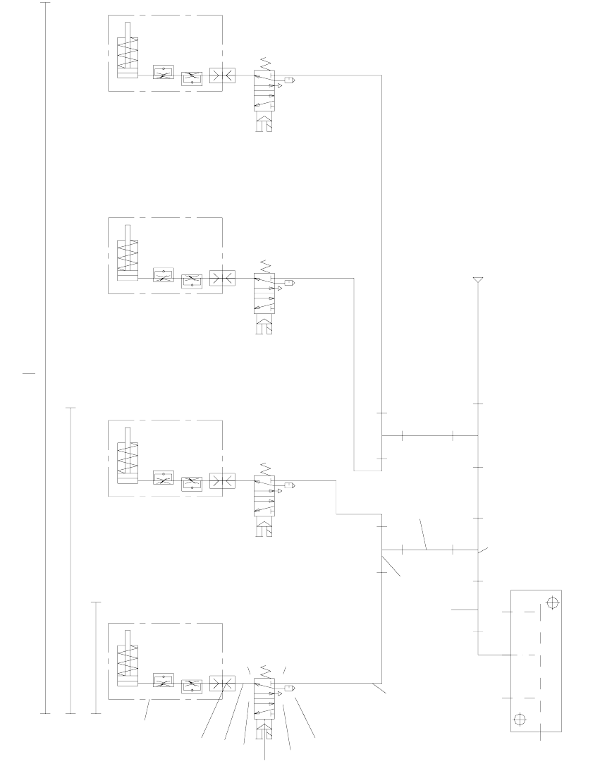
2.8 Pneumatic diagram
2
Fig. 2.8 - 1 Pneumatic drawing for ceramic substrate centering unit, HF series, HS-60, S-27 HM (00119671-010501)
Ø8x1.25
p=5.5 bar
Conveyor air distributor
10
10
5
9
8
7
6
6
5
4
3
2
1
HS60 DC + HF DC
S27HM DC + HS60 + HF
Ceramic substrate
centering assembly
5
1
4
3
2
5
1
4
3
2
5
1
4
3
2
5
1
4
2
3
Lock connections 4 and 5 using the item 10 screws.
S27HM
Ceramic substrate centering SIPLACE S-27 HM 2 Retrofit instructions: ceramic substrate centering for SIPLACE S-27 HM
12/2004 Edition
57
2.9 Circuit diagram
2
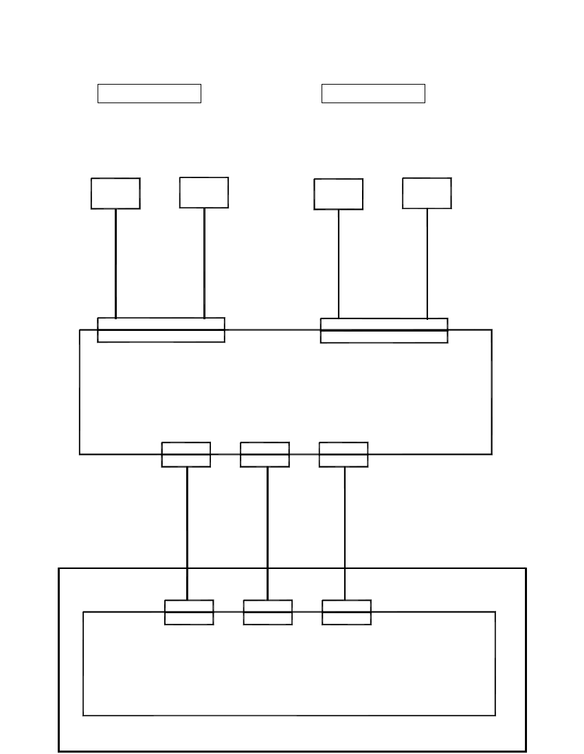
Fig. 2.9 - 1 SIPLACE S-27 HM wiring diagram
Conversion board, assembly trough (kt)
00359426
Conveyor control (kc)
00 358068
Overview: Connecting the ceramic substrate centering
00 363417
00 363416
X11
X11
X12
X12
B 1
00 369723 - W1
X34kt
X51
X51 X52
X52
Z 1
00 369723-W2
X34kt
Sensor
Ceramic
substrate cent. 1
Conveyor track 1
Valve
Ceramic
substrate cent. 1
00 363418
X13
X13
X35kt
X53
X53
00 369723 - W1
B 2
00 369723-W2
X35kt
Z 2
substrate cent. 2 substrate cent. 2
Conveyor track 2
Sensor
Ceramic
Valve
Ceramic
Control, complete S-27 HM (item no.: 00358068-xx)
2 Retrofit instructions: ceramic substrate centering for SIPLACE S-27 HM Ceramic substrate centering SIPLACE S-27 HM
12/2004 Edition
58
2.10 Activating the option
2.10.1 Overview
All though the fully installed "mechanical ceramic substrate centering" option hardware is auto-
matically detected by the software due by the presence of the coding plug (plug-in connection
between the option and the conveyor control), it still has to be activated in the SITEST program.
The mechanical ceramic substrate centering is always combined with fiducial position detection
on the substrate.
The position detection is carried out with the PCB vision camera with normal lighting or the
optional oblique lighting. If the optional multi-color PCB camera is used on the machine, rather
than the above PCB vision camera, then the fiducials are always centered with this camera by
default. The oblique lighting option is not used in this case.
Please note: 2
– If the mechanical ceramic substrate centering hardware has been installed, it must also be ac-
tivated in the "Machine Configuration" menu.
– When the mechanical ceramic substrate centering is deactivated in the Machine Configuration
menu, then it must first be fully removed from both processing areas of the affected conveyor,
i.e. the plug-in connections on the option must also be detached from the conveyor control.
The conveyor modules must also be converted on the PCB conveyor in parallel.
2
2
2
2
2
2
2
2
2
2
2
2
2