CP-642ME-05.pdf - 第5页
配置図 O v e r v i e w CP-642ME P ARTS LIST ver05 配置図 O v e r v i e w 5 . L o a d i n g u n i t ( W Q L , G V L ) 6 . 1 . B o a r d c l a m p i n g u n i t ( W S S ) 6 . 2 . B o a r d c l a m p i n g u n i t ( W S S ) 7…

納入後第三者への転売をお考えの際には、必ず事前に弊社へご連絡下さい。
Consult FUJI beforehand if you are considering selling
this equipment to a third party after it has been installed.
パ−ツリストをご利用される前に
1.部品は、図番、コ−ド番号、個数、品名、および規格で発注下さい。
この発注方法以外で発注された場合は発注部品に間違いが生じる恐れがあります。
2.本パ−ツリストは改良のため予告なく変更することがあります。
3.リスト左端の番号が抜けて順番に記載されていない箇所がありますが、これは記載モレや作成途中ではなく
今まで使用していた部品が設計変更により使用されなくなり表から削除されたものです。同時にイラスト内の部品も削除されています。
4.ボルト類,ナット類およびワッシャ類などは種類のみ記載してあります。それぞれの個数は記載せず空欄となっています。
図面原稿 : 1999年 5月
05JE発行 : 1999年 9月
Before Using the Parts List
1. Specify a part number, code number, quantity, part name and rating when ordering parts.
2. This parts manual is subject to change without notice.
3. There are cases where there are no numbers in the left hand column of the parts list. This is not because they were omitted or
the list is incomplete but because the parts to which the numbers applied were eliminated due to a design change.
In such cases the parts have also been removed from the figures.
4. Only the part types are described for nuts, bolts and washers. The quantity column is left blank.
Blueprints created : MAY 1999
05JE released : SEP 1999
5.設計変更した部品(図番の下一桁をカウントアップした部品)は設計変更前の部品と互換です。
しかし、設計変更前の部品は設計変更後の部品と互換であるとは限りません。
例:ABC1231はABC1230と互換であるが、ABC1230がABC1231と互換であるとは限りません。
5. A redesigned part (the last digit of the part number is incremented) is compatible with a part before the redesign.
However,the original part is not always compatible with the revised part,e.i.,ABC1231 is compatible with ABC1230,but
ABC1230 is not always compatible with ABC1231.
TOP
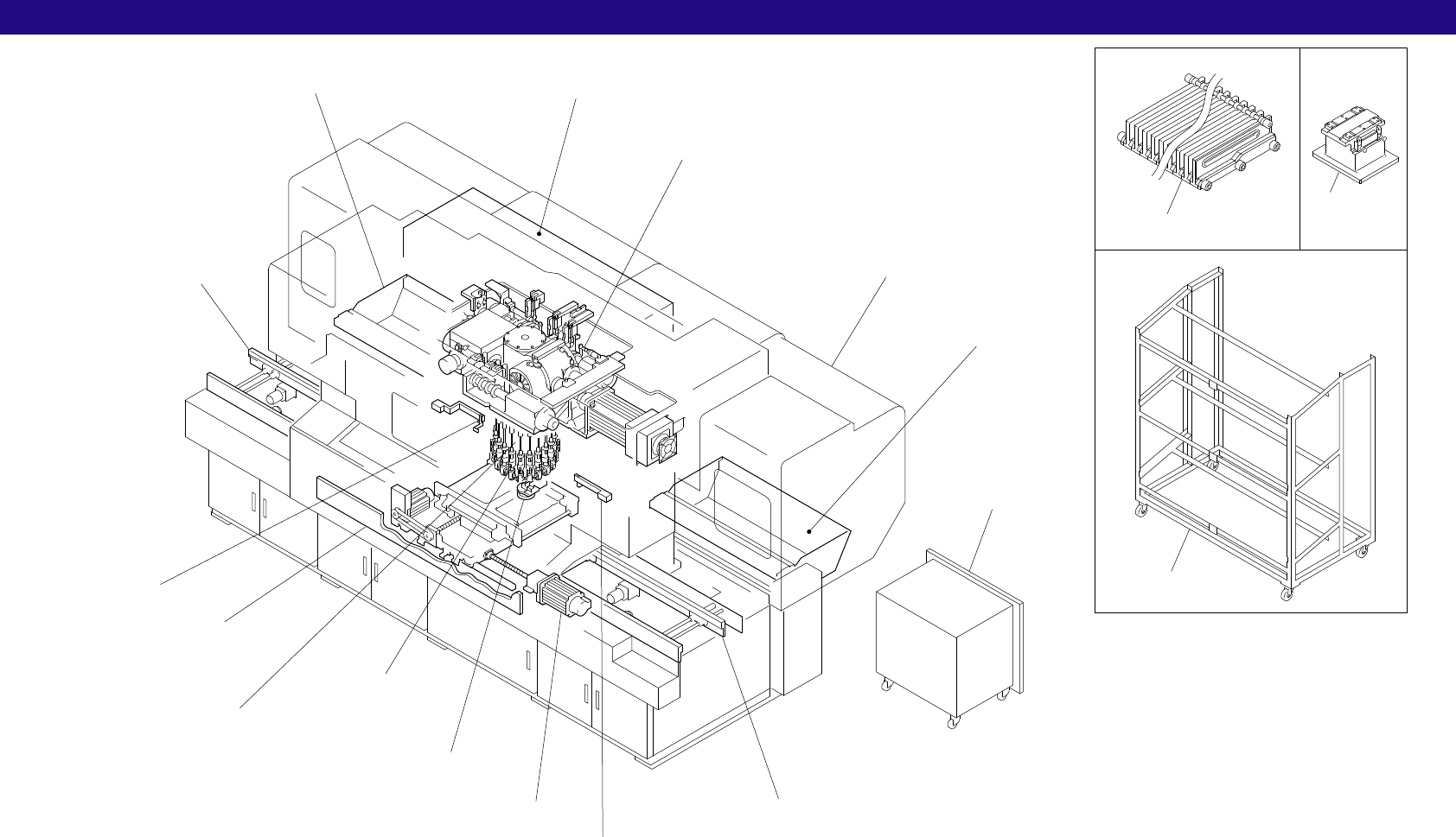
配置図 Overview
CP-642ME PARTS LIST ver05
配置図
Overview
5.Loading unit(WQL,GVL)
6.1.Board clamping unit(WSS)
6.2.Board clamping unit(WSS)
7.X slide(WSX)
8.1.Y slide(WSY)
8.2.Y slide(WSY)
9.1.Z table(WSZ)
9.2.Z table(WSZ)
42.Vacuum backup(Option)(WSZ)
12.Station 1(Parts pick up)(WPL)
13.Station 2(Parts check)(WGZ)
14.Station 5(Nozzle theta positioning)(WPP)
15.1.Station 6(Vision processing)(WGC)
15.2.Station 6(Vision processing)(WGC)
16.Station 10(Fine theta),
Station 12(Reverse fine theta)(WPQ)
17.Station 3(Pre theta),
Station 13(Reverse pre theta)(WPQ)
18.Station 16(Parts eject),
Waste tape cutter(WPU,WPK)
19.Station 17(Nozzle pre change check),
Station 18(Nozzle change),
Station 19(Nozzle post change check)(WPM)
37.Feeder rack(WCY)
4.Out conveyor(WQC)
33.Out conveyor(Right-to-left board flow)(Option)(WQC)
35.Out conveyor(Board flow changeover manual)(Option)(WQC)
44.Out conveyor(Cover)(Option)(WQC)
3.In conveyor(WQC)
32.In conveyor(Right-to-left board flow)
(Option)(WQC)
34.In conveyor(Board flow changeover manual)
(Option)(WQC)
43.In conveyor(Cover)(Option)(WQC)
23.1.Noise reduction box(WPV)
23.2.Noise reduction box(WPV)
25.Cam box 1(WPA)
26.Cam box 2(WPA)
27.1.Cam box 3(WPA)
27.2.Cam box 3(WPA)
1.Nozzles(WPH)
2.Placing head,Drum(WPH)
20.Device table D1(1∼50)(WSD)
21.Device table D2(51∼100)(WSD)
10.Optical correction(WGP)
36.Feeder stand(WCY)
11.Feeder check sensor(WGZ)
11.Feeder check sensor(WGZ)
38.Feeder setting
jig(WPJ)
22.1.Noise reduction cover(WAF)
22.2.Noise reduction cover(WAF)
22.3.Noise reduction cover(WAF)
24.Dust collector(WPV)
x25
29.Body(WAB)
30.Cover(WPZ)
28.Pneumatic circuit diagram(WPI)
31.Air device(WPI)
39.Shutter(Option)(WAF)
40.1.Fence(Option)(WAF)
40.2.Fence(Option)(WAF)
41.1.UK fence(Option)(WAF)
41.2.UK fence(Option)(WAF)
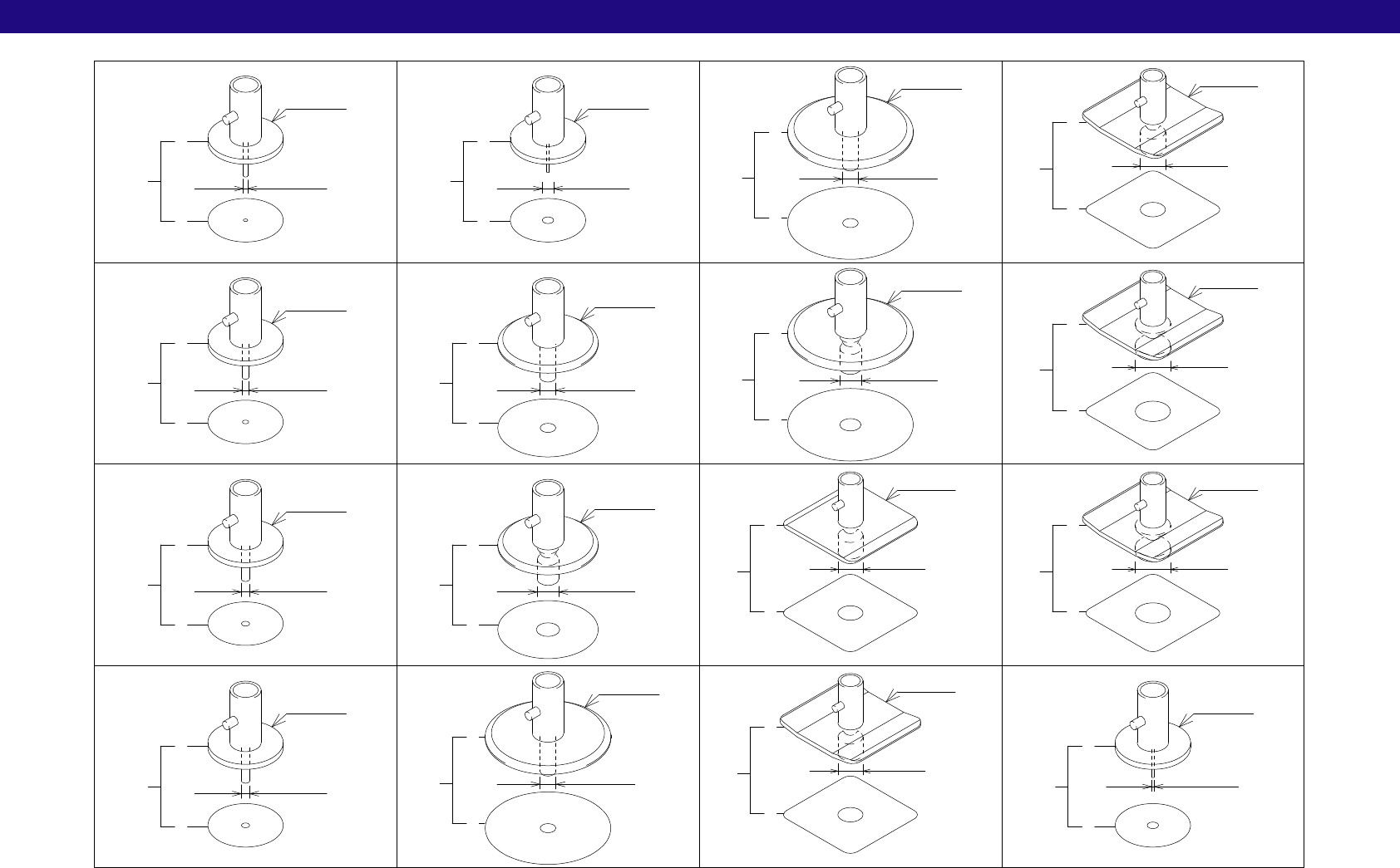
1.ノズル一覧 Nozzles(WPH)
CP-642ME PARTS LIST ver05
1-1
1.ノズル一覧(WPH)
1.Nozzles(WPH)
x1.5
R012-007
M012-013
φ1.3
φ0.41
φ7.0
φ3.75
44
45
43
11
12
10
R012-010
φ1.0
5
6
4
R012-013
φ1.3
8
9
7
φ0.71
2
3
1
47
48
46
R012-004
φ2.5
R016-025
17
18
16
φ3.75
R016-037
20
21
19
φ2.5
R020-025
23
24
22
φ2.5
M020-025
26
27
25
R020-037
B022-070
29
30
28
φ5.0
32
33
31
S020-050
φ7.0
41
42
40
S022-070
φ5.0
38
39
37
B022-050
φ5.0
35
36
34
S022-050
φ1.81
14
15
13
R012-018
φ20
φ12φ12
□22
φ12
φ12
φ12
φ16
φ16
φ20
φ20
□20
□22
□22
□22
φ12