SMU_dat-sw-en.pdf - 第11页
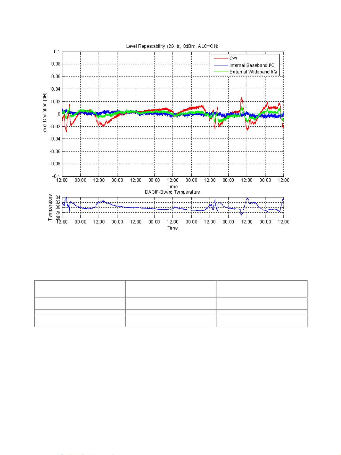
Version 08.00, Januar y 2012 Rohde & Schwarz R&S ® SMU200A Vector Signal Generator 11 Measured level repeatability over 6 days with random settings between measurements (DACIF board temperature: intern al tempera…
Version 08.00, January 2012
10 Rohde & Schwarz R&S
®
SMU200A Vector Signal Generator
Measured level data
0.5 1 1.5 2 2.5 3 3.5 4 4.5 5 5.5 6
x 10
9
10
12
14
16
18
20
22
24
26
28
30
RF frequency / Hz
Level / dBm
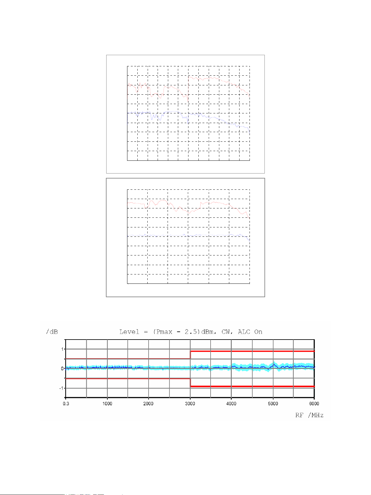
Max. available output power with frequency option B106,
Attenuator Mode Normal (lower trace) and High Power (upper trace)
0.5 1 1.5 2 2.5 3
x 10
9
10
12
14
16
18
20
22
24
26
28
30
RF frequency / Hz
Level / dBm
Max. available output power with frequency option B103,
Attenuator Mode Normal (lower trace) and High Power (upper trace)
Measured maximum available output level versus frequency.
Measured level uncertainty versus frequency.
Version 08.00, January 2012
Rohde & Schwarz R&S
®
SMU200A Vector Signal Generator 11
Measured level repeatability over 6 days with random settings between measurements
(DACIF board temperature: internal temperature test point, variations caused by changes of ambient temperature).
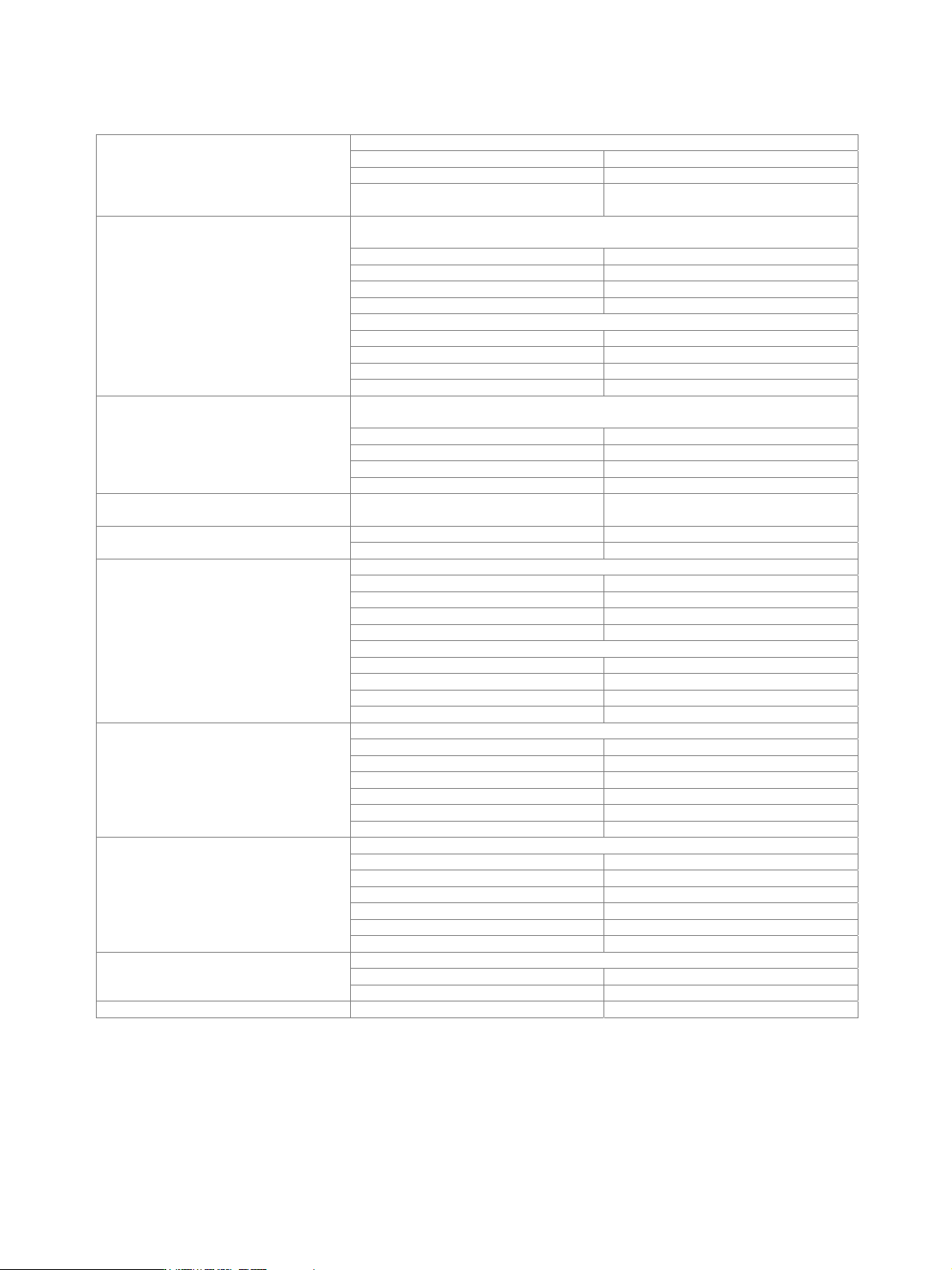
Level sweep
Operating modes digital sweep in discrete steps auto, single, step,
external single, external step,
manual or external trigger
Sweep range level range of attenuator modes
normal or high power
Step width logarithmic 0.1 dB to 20 dB per step
range 10 ms to 10 s Dwell time
resolution 0.1 ms
Version 08.00, January 2012
12 Rohde & Schwarz R&S
®
SMU200A Vector Signal Generator
Spectral purity
standard, unmodulated
level < 8 dBm < –30 dBc
level < 13 dBm < –30 dBc (typ.)
Harmonics
with R&S
®
SMU-B31 or R&S
®
SMU-B36
option, level < 12 dBm
< –30 dBc
level > –50 dBm, CW, vector modulation (full-scale DC input),
> 10 kHz offset from carrier and outside the modulation spectrum
0.3 MHz f 200 MHz < –77 dBc
200 MHz < f 1500 MHz < –80 dBc
1500 MHz < f 3000 MHz < –74 dBc
f > 3000 MHz < –68 dBc
> 850 kHz offset from carrier and outside the modulation spectrum
0.3 MHz f 200 MHz < –77 dBc
200 MHz < f 1500 MHz < –86 dBc
1500 MHz < f 3000 MHz < –80 dBc
Nonharmonics
f > 3000 MHz < –74 dBc
level > –50 dBm, CW, vector modulation (full-scale DC input),
> 10 kHz offset from carrier and outside the modulation spectrum
0.3 MHz f 200 MHz < –77 dBc (–87 dBc (typ.))
200 MHz < f 1500 MHz < –90 dBc
1500 MHz < f 3000 MHz < –84 dBc
Nonharmonics with R&S
®
SMU-B22 option
f > 3000 MHz < –78 dBc
Power supply and mechanically related
nonharmonics
at RF = 1 GHz,
50 Hz to 10 kHz from carrier
< –70 dBc
1500 MHz < f 3000 MHz < –74 dBc Subharmonics
f > 3000 MHz < –50 dBc
> 10 MHz carrier offset, 1 Hz measurement bandwidth, CW
20 MHz f 200 MHz < –146 dBc (–149 dBc (typ.))
200 MHz < f 1500 MHz < –150 dBc (–153 dBc (typ.))
1.5 GHz < f 3 GHz < –148 dBc (–151 dBc (typ.))
f > 3 GHz < –146 dBc (–149 dBc (typ.))
vector modulation with full-scale DC input, 3 dB I/Q input gain
20 MHz f 200 MHz < –143 dBc (–146 dBc (typ.))
200 MHz < f 1500 MHz < –146 dBc (–149 dBc (typ.))
1.5 GHz < f 3 GHz < –145 dBc (–148 dBc (typ.))
Wideband noise
f > 3 GHz < –143 dBc (–146 dBc (typ.))
20 kHz carrier offset, 1 Hz measurement bandwidth, CW
20 MHz f 200 MHz < –128 dBc (–132 dBc (typ.))
f = 1 GHz < –131 dBc (–135 dBc (typ.))
f = 2 GHz < –125 dBc (–129 dBc (typ.))
f = 3 GHz < –121 dBc (–125 dBc (typ.))
f = 4 GHz < –119 dBc (–123 dBc (typ.))
SSB phase noise
f = 6 GHz < –115 dBc (–119 dBc (typ.))
20 kHz carrier offset, 1 Hz measurement bandwidth, CW
20 MHz f 200 MHz < –135 dBc (–138 dBc (typ.))
f = 1 GHz < –136 dBc (–139 dBc (typ.))
f = 2 GHz < –130 dBc (–133 dBc (typ.))
f = 3 GHz < –126 dBc (–129 dBc (typ.))
f = 4 GHz < –124 dBc (–127 dBc (typ.))
SSB phase noise with R&S
®
SMU-B22
option
f = 6 GHz < –120 dBc (–123 dBc (typ.))
RMS value at f = 1 GHz
300 Hz to 3 kHz < 1 Hz
Residual FM
20 Hz to 23 kHz < 4 Hz
Residual AM RMS value from 20 Hz to 23 kHz < 0.02 %