SMU_dat-sw-en.pdf - 第13页
Version 08.00, Januar y 2012 Rohde & Schwarz R&S ® SMU200A Vector Signal Generator 13 Measur ed SSB phase noise, I / Q modulate d -160 -150 -140 -130 -120 -110 -100 -90 -80 -70 -60 -50 -40 1,0E+00 1,0E+01 1,0E+02…
Version 08.00, January 2012
12 Rohde & Schwarz R&S
®
SMU200A Vector Signal Generator
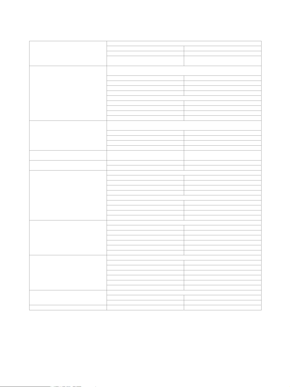
Spectral purity
standard, unmodulated
level < 8 dBm < –30 dBc
level < 13 dBm < –30 dBc (typ.)
Harmonics
with R&S
®
SMU-B31 or R&S
®
SMU-B36
option, level < 12 dBm
< –30 dBc
level > –50 dBm, CW, vector modulation (full-scale DC input),
> 10 kHz offset from carrier and outside the modulation spectrum
0.3 MHz f 200 MHz < –77 dBc
200 MHz < f 1500 MHz < –80 dBc
1500 MHz < f 3000 MHz < –74 dBc
f > 3000 MHz < –68 dBc
> 850 kHz offset from carrier and outside the modulation spectrum
0.3 MHz f 200 MHz < –77 dBc
200 MHz < f 1500 MHz < –86 dBc
1500 MHz < f 3000 MHz < –80 dBc
Nonharmonics
f > 3000 MHz < –74 dBc
level > –50 dBm, CW, vector modulation (full-scale DC input),
> 10 kHz offset from carrier and outside the modulation spectrum
0.3 MHz f 200 MHz < –77 dBc (–87 dBc (typ.))
200 MHz < f 1500 MHz < –90 dBc
1500 MHz < f 3000 MHz < –84 dBc
Nonharmonics with R&S
®
SMU-B22 option
f > 3000 MHz < –78 dBc
Power supply and mechanically related
nonharmonics
at RF = 1 GHz,
50 Hz to 10 kHz from carrier
< –70 dBc
1500 MHz < f 3000 MHz < –74 dBc Subharmonics
f > 3000 MHz < –50 dBc
> 10 MHz carrier offset, 1 Hz measurement bandwidth, CW
20 MHz f 200 MHz < –146 dBc (–149 dBc (typ.))
200 MHz < f 1500 MHz < –150 dBc (–153 dBc (typ.))
1.5 GHz < f 3 GHz < –148 dBc (–151 dBc (typ.))
f > 3 GHz < –146 dBc (–149 dBc (typ.))
vector modulation with full-scale DC input, 3 dB I/Q input gain
20 MHz f 200 MHz < –143 dBc (–146 dBc (typ.))
200 MHz < f 1500 MHz < –146 dBc (–149 dBc (typ.))
1.5 GHz < f 3 GHz < –145 dBc (–148 dBc (typ.))
Wideband noise
f > 3 GHz < –143 dBc (–146 dBc (typ.))
20 kHz carrier offset, 1 Hz measurement bandwidth, CW
20 MHz f 200 MHz < –128 dBc (–132 dBc (typ.))
f = 1 GHz < –131 dBc (–135 dBc (typ.))
f = 2 GHz < –125 dBc (–129 dBc (typ.))
f = 3 GHz < –121 dBc (–125 dBc (typ.))
f = 4 GHz < –119 dBc (–123 dBc (typ.))
SSB phase noise
f = 6 GHz < –115 dBc (–119 dBc (typ.))
20 kHz carrier offset, 1 Hz measurement bandwidth, CW
20 MHz f 200 MHz < –135 dBc (–138 dBc (typ.))
f = 1 GHz < –136 dBc (–139 dBc (typ.))
f = 2 GHz < –130 dBc (–133 dBc (typ.))
f = 3 GHz < –126 dBc (–129 dBc (typ.))
f = 4 GHz < –124 dBc (–127 dBc (typ.))
SSB phase noise with R&S
®
SMU-B22
option
f = 6 GHz < –120 dBc (–123 dBc (typ.))
RMS value at f = 1 GHz
300 Hz to 3 kHz < 1 Hz
Residual FM
20 Hz to 23 kHz < 4 Hz
Residual AM RMS value from 20 Hz to 23 kHz < 0.02 %

Version 08.00, January 2012
Rohde & Schwarz R&S
®
SMU200A Vector Signal Generator 13
Measured SSB phase noise, I
/
Q modulated
-160
-150
-140
-130
-120
-110
-100
-90
-80
-70
-60
-50
-40
1,0E+00 1,0E+01 1,0E+02 1,0E+03 1,0E+04 1,0E+05 1,0E+06 1,0E+07
Offset frequency
/
Hz
SSB phase noise / dBc (1Hz meas. bandwidth)
5.7 GHz
2.1 GHz
850 MHz
100 MHz
Measured SSB phase noise, unmodulated
-160
-150
-140
-130
-120
-110
-100
-90
-80
-70
-60
-50
-40
1,0E+00 1,0E+01 1,0E+02 1,0E+03 1,0E+04 1,0E+05 1,0E+06 1,0E+07
Offset frequency
/
Hz
SSB phase noise / dBc (1Hz meas. bandwidth)
5.7 GHz
2.1 GHz
850 MHz
100 MHz
–180
–170
–160
–150
–140
–130
–120
–110
–100
–90
–80
–70
–60
–50
–40
1 10 100 1k 10k 100k 1M 10M
Offset frequency / Hz
SSB phase noise / dBc (1 Hz)
Standard performance
Enhanced phase noise performance with B22 option
Measured SSB phase noise, f = 1 GHz, comparison of standard performance
and performance with R&S
®
SMU-B22 option.
Version 08.00, January 2012
14 Rohde & Schwarz R&S
®
SMU200A Vector Signal Generator
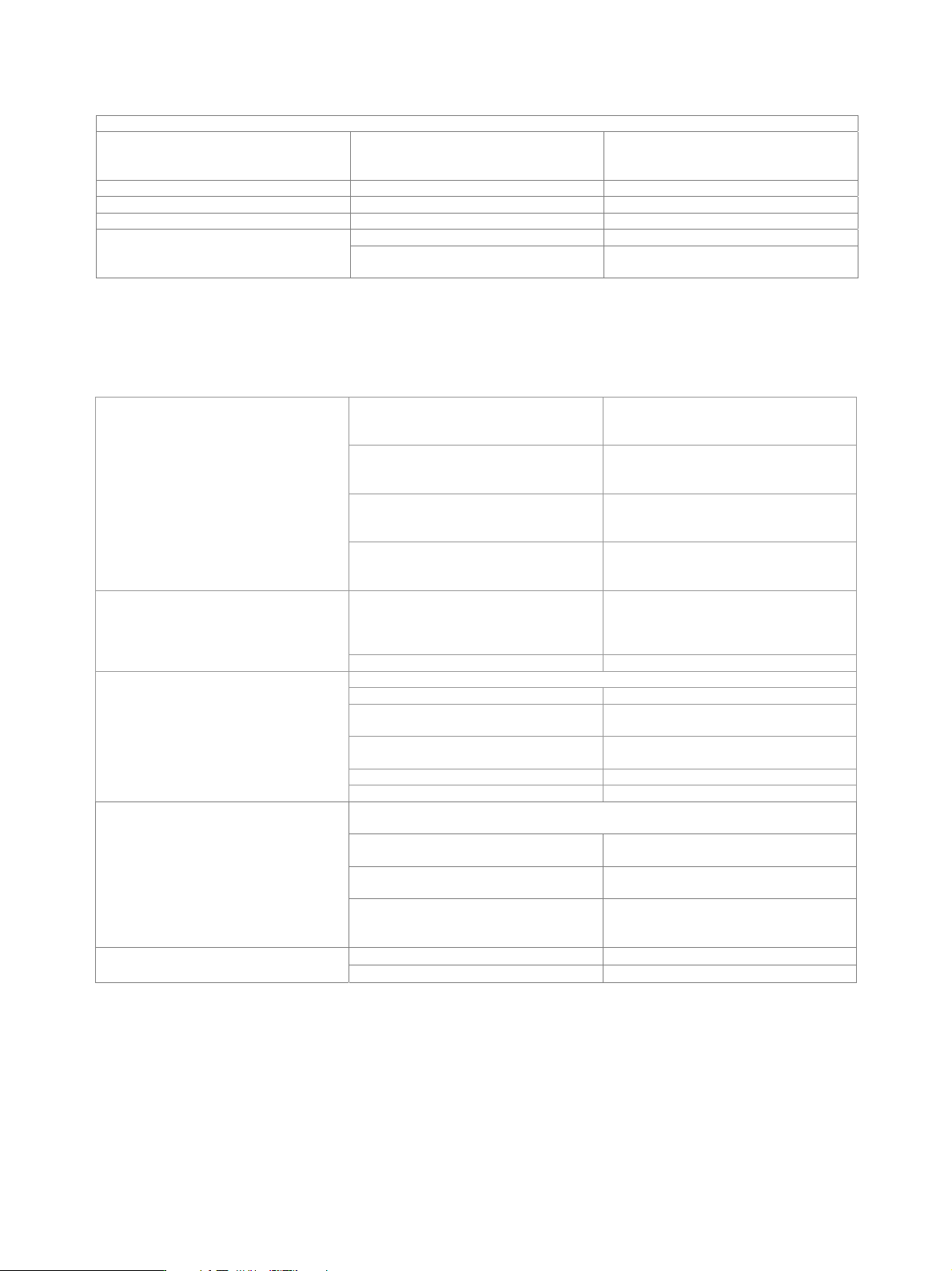
List mode
Frequency and level values can be stored in a list and set in an extremely short amount of time.
Operating modes automatic, single sweep, manual or
external trigger, fast hopping with
immediate and external trigger
Max. number of channels 10000
Dwell time 1 ms to 1 s
Resolution 0.1 ms
after external trigger see frequency and level data Setting time
additional trigger delay in two-path units,
both paths operated in list mode
< 200 µs
Phase coherence (R&S
®
SMU-B90 option)
The R&S
®
SMU-B90 provides phase-coherent RF outputs of two or more RF paths for one or more instruments with I/Q modulation.
The R&S
®
SMU-B90 option can be installed in any R&S
®
SMU200A with serial number 103001 or higher.
internal This mode corresponds to normal
operation. Each RF path uses its internal
local oscillator.
external An external signal is used for path A. With
a two-path instrument, the internal local
oscillator signal is used for path B.
coupled A –> B The local oscillator signal of path A is also
used for path B (only for two-path
instruments).
Coupling modes
externally coupled A –> B An external signal is input at the LO IN
connector and used for the coupled paths
A and B (only for two-path instruments).
The internal local oscillator signal used
with path A is also available on the LO
OUT connector (in order to couple two
instruments).
on
LO out state
The LO OUT signal is switched off. off
internal mode (no LO coupling)
underrange 100 kHz to < 300 kHz
R&S
®
SMU-B102,
R&S
®
SMU-B202
up to 2 GHz
R&S
®
SMU-B103,
R&S
®
SMU-B203,
up to 3 GHz
R&S
®
SMU-B104 up to 4 GHz
Frequency range
R&S
®
SMU-B106 up to 6 GHz
external modes, coupled A –> B,
externally coupled A –> B
R&S
©
SMU-B102 and
R&S
©
SMU-B202
200 MHz to 2 GHz
R&S
©
SMU-B103 and
R&S
©
SMU-B203
200 MHz to 3 GHz
other configurations Coupling is possible within the smallest
common frequency range of all RF paths
to be coupled.
LO IN 10 dBm to 16 dBm (nom.) Levels of external local oscillator signals
LO OUT 13 dBm (nom.)