SMU_dat-sw-en.pdf - 第15页
Version 08.00, Januar y 2012 Rohde & Schwarz R&S ® SMU200A Vector Signal Generator 15 drift versus temperature 0.1° (nom.) when ambient temperature changes by 1 °C versus time 0.02°/h (nom.) versus level 2°/dB (n…

Version 08.00, January 2012
14 Rohde & Schwarz R&S
®
SMU200A Vector Signal Generator
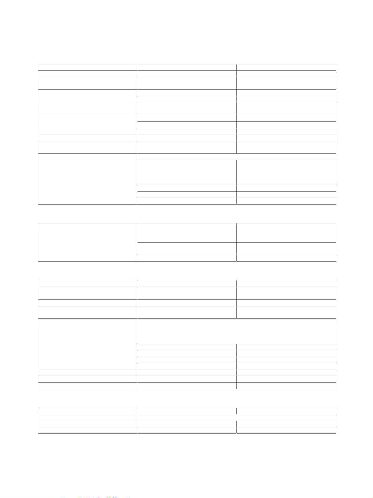
List mode
Frequency and level values can be stored in a list and set in an extremely short amount of time.
Operating modes automatic, single sweep, manual or
external trigger, fast hopping with
immediate and external trigger
Max. number of channels 10000
Dwell time 1 ms to 1 s
Resolution 0.1 ms
after external trigger see frequency and level data Setting time
additional trigger delay in two-path units,
both paths operated in list mode
< 200 µs
Phase coherence (R&S
®
SMU-B90 option)
The R&S
®
SMU-B90 provides phase-coherent RF outputs of two or more RF paths for one or more instruments with I/Q modulation.
The R&S
®
SMU-B90 option can be installed in any R&S
®
SMU200A with serial number 103001 or higher.
internal This mode corresponds to normal
operation. Each RF path uses its internal
local oscillator.
external An external signal is used for path A. With
a two-path instrument, the internal local
oscillator signal is used for path B.
coupled A –> B The local oscillator signal of path A is also
used for path B (only for two-path
instruments).
Coupling modes
externally coupled A –> B An external signal is input at the LO IN
connector and used for the coupled paths
A and B (only for two-path instruments).
The internal local oscillator signal used
with path A is also available on the LO
OUT connector (in order to couple two
instruments).
on
LO out state
The LO OUT signal is switched off. off
internal mode (no LO coupling)
underrange 100 kHz to < 300 kHz
R&S
®
SMU-B102,
R&S
®
SMU-B202
up to 2 GHz
R&S
®
SMU-B103,
R&S
®
SMU-B203,
up to 3 GHz
R&S
®
SMU-B104 up to 4 GHz
Frequency range
R&S
®
SMU-B106 up to 6 GHz
external modes, coupled A –> B,
externally coupled A –> B
R&S
©
SMU-B102 and
R&S
©
SMU-B202
200 MHz to 2 GHz
R&S
©
SMU-B103 and
R&S
©
SMU-B203
200 MHz to 3 GHz
other configurations Coupling is possible within the smallest
common frequency range of all RF paths
to be coupled.
LO IN 10 dBm to 16 dBm (nom.) Levels of external local oscillator signals
LO OUT 13 dBm (nom.)

Version 08.00, January 2012
Rohde & Schwarz R&S
®
SMU200A Vector Signal Generator 15
drift
versus temperature 0.1° (nom.)
when ambient temperature changes
by 1 °C
versus time 0.02°/h (nom.)
versus level 2°/dB (nom.)
setting range
(with baseband phase offset)
0.00° to 359.99°
Phase
setting resolution 0.01°
Version 08.00, January 2012
16 Rohde & Schwarz R&S
®
SMU200A Vector Signal Generator
Analog modulation
Internal modulation generator
Frequency range 0.1 Hz to 1 MHz
Resolution of setting 0.1 Hz
Frequency uncertainty < 0.012 Hz
+
relative deviation of reference frequency
up to 100 kHz < 0.1 dB Frequency response
up to 1 MHz < 1 dB
Distortion up to 100 kHz at R
L
> 200 ,
level = 1 V (V
p
)
< 0.1 %
V
p
at LF connector, R
L
> 200 1 mV to 3 V
resolution 1 mV
Output voltage
setting uncertainty at 1 kHz < (1 % of reading + 1 mV)
Output impedance 16
Frequency setting time to within < 1 × 10
−
7
, with GUI update
stopped, after IEC/IEEE bus delimiter
< 3 ms
digital sweep in discrete steps
operating modes
automatic, step, single,
external single, external step,
manual or external trigger,
linear or logarithmic spacing
sweep range entire frequency range
linear step width entire frequency range
Sweep
logarithmic step width 0.01 % to 100 % per step
Input for external modulation signals
input impedance
high (> 100 k),
switchable to 50 with R&S
®
SMU-B20 or
R&S
®
SMU-B22 option
input sensitivity (peak value for set
modulation depth or deviation)
1 V
Modulation input
EXT MOD
maximum permissible input voltage ±10 V
Amplitude modulation
Operating modes internal, external AC/DC
Modulation depth modulation is clipped at high levels if
maximum PEP is reached
0 % to 100 %
Resolution 0.1 %
Setting uncertainty attenuator mode: auto,
f
mod
= 1 kHz and m < 80 %
< (1 % of reading + 1 %)
PEP in specified range,
attenuator mode: auto
f 3 GHz, at f
mod
= 1 kHz, m = 30 % < 0.5 %
m = 80 % < 0.8 %
f > 3 GHz, at f
mod
= 1 kHz, m = 30 % < 1 %
AM distortion
m = 80 % < 1.6 %
Modulation frequency range DC, 20 Hz to 500 kHz
Modulation frequency response AC mode, 20 Hz to 500 kHz < 1 dB
Synchronous M at AM m = 30 %, f
mod
= 1 kHz, peak value < 0.1 rad
Wideband amplitude modulation
Operating modes modulation input I external DC
Modulation frequency response as with I/Q modulation – external wideband I/Q
Input impedance 50
Input sensitivity peak voltage for 100 % AM 0.25 V