SMU_dat-sw-en.pdf - 第17页
Version 08.00, Januar y 2012 Rohde & Schwarz R&S ® SMU200A Vector Signal Generator 17 Pulse modulation Operating modes external, internal (duty cycle approx. 1:1) On/off ratio > 70 dB Rise/fall time 10 %/90 % …
Version 08.00, January 2012
16 Rohde & Schwarz R&S
®
SMU200A Vector Signal Generator
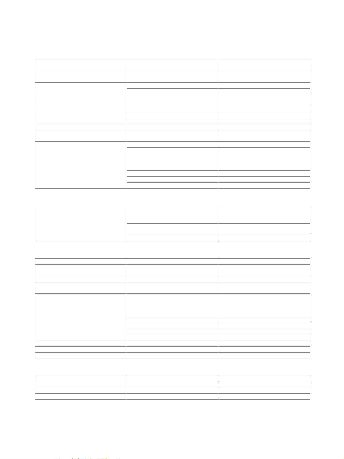
Analog modulation
Internal modulation generator
Frequency range 0.1 Hz to 1 MHz
Resolution of setting 0.1 Hz
Frequency uncertainty < 0.012 Hz
+
relative deviation of reference frequency
up to 100 kHz < 0.1 dB Frequency response
up to 1 MHz < 1 dB
Distortion up to 100 kHz at R
L
> 200 ,
level = 1 V (V
p
)
< 0.1 %
V
p
at LF connector, R
L
> 200 1 mV to 3 V
resolution 1 mV
Output voltage
setting uncertainty at 1 kHz < (1 % of reading + 1 mV)
Output impedance 16
Frequency setting time to within < 1 × 10
−
7
, with GUI update
stopped, after IEC/IEEE bus delimiter
< 3 ms
digital sweep in discrete steps
operating modes
automatic, step, single,
external single, external step,
manual or external trigger,
linear or logarithmic spacing
sweep range entire frequency range
linear step width entire frequency range
Sweep
logarithmic step width 0.01 % to 100 % per step
Input for external modulation signals
input impedance
high (> 100 k),
switchable to 50 with R&S
®
SMU-B20 or
R&S
®
SMU-B22 option
input sensitivity (peak value for set
modulation depth or deviation)
1 V
Modulation input
EXT MOD
maximum permissible input voltage ±10 V
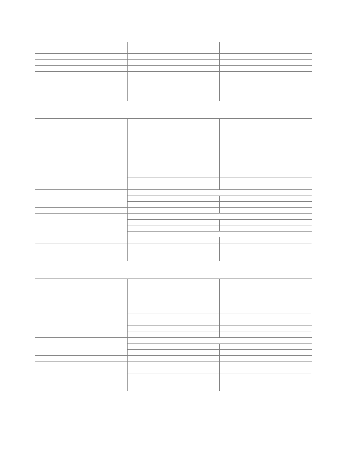
Amplitude modulation
Operating modes internal, external AC/DC
Modulation depth modulation is clipped at high levels if
maximum PEP is reached
0 % to 100 %
Resolution 0.1 %
Setting uncertainty attenuator mode: auto,
f
mod
= 1 kHz and m < 80 %
< (1 % of reading + 1 %)
PEP in specified range,
attenuator mode: auto
f 3 GHz, at f
mod
= 1 kHz, m = 30 % < 0.5 %
m = 80 % < 0.8 %
f > 3 GHz, at f
mod
= 1 kHz, m = 30 % < 1 %
AM distortion
m = 80 % < 1.6 %
Modulation frequency range DC, 20 Hz to 500 kHz
Modulation frequency response AC mode, 20 Hz to 500 kHz < 1 dB
Synchronous M at AM m = 30 %, f
mod
= 1 kHz, peak value < 0.1 rad
Wideband amplitude modulation
Operating modes modulation input I external DC
Modulation frequency response as with I/Q modulation – external wideband I/Q
Input impedance 50
Input sensitivity peak voltage for 100 % AM 0.25 V
Version 08.00, January 2012
Rohde & Schwarz R&S
®
SMU200A Vector Signal Generator 17
Pulse modulation
Operating modes external,
internal (duty cycle approx. 1:1)
On/off ratio > 70 dB
Rise/fall time 10 %/90 % of RF amplitude 1 µs (typ.)
Pulse repetition frequency 0 Hz to 100 kHz
Video crosstalk spectral line of fundamental of 100 kHz
square-wave modulation
< −30 dBc
input level rising 1.7 V, falling 1.1 V (typ.)
input impedance > 10 k
Modulation input
EXT MOD A/B
polarity selectable
Frequency modulation (R&S
®
SMU-B20 or R&S
®
SMU-B22 option)
Operating modes internal, external, internal + external,
AC/DC, normal,
low noise (with R&S
®
SMU-B22 only)
0.3 MHz f 200 MHz rm = 1
200 MHz < f 375 MHz rm = 0.25
375 MHz < f 750 MHz rm = 0.5
750 MHz < f 1500 MHz rm = 1
1500 MHz < f 3000 MHz rm = 2
FM/M range multiplier
f > 3000 MHz rm = 4
FM mode: normal rm × 10 MHz Maximum deviation
FM mode: low noise rm × 100 kHz
Resolution < 200 ppm, min. rm × 0.1 Hz
f
mod
= 10 kHz, deviation half of maximum deviation
internal < (1.5 % of reading + 20 Hz)
Setting uncertainty
external < (2.0 % of reading + 20 Hz)
FM distortion f
mod
= 10 kHz and 1 MHz deviation < 0.1 %
FM mode: normal
10 Hz to 100 kHz < 0.5 dB
10 Hz to 10 MHz < 3 dB
FM mode: low noise
Modulation frequency response
10 Hz to 100 kHz < 3 dB
40 kHz deviation, f
mod
= 1 kHz, f > 5 MHz < 0.1 % Synchronous AM
f > 3 GHz < 0.2 %
Carrier frequency offset at FM < 0.2 % of set deviation
Phase modulation (R&S
®
SMU-B20 or R&S
®
SMU-B22 option)
Operating mode internal, external, internal + external,
AC/DC, high bandwidth,
high deviation,
low noise (with R&S
®
SMU-B22 only)
M mode: high deviation rm × 20.0 rad
M mode: high bandwidth rm × 1.0 rad
Maximum deviation
M mode: low noise rm × 0.25 rad
M mode: high deviation < 200 ppm, min. rm × 20 µrad
M mode: high bandwidth < 0.1 %, min. rm × 20 µrad
Resolution
M mode: low noise < 200 ppm, min. rm × 20 µrad
f
mod
= 10 kHz, deviation half of maximum deviation
internal < (1.5 % of reading + 0.01 rad)
Setting uncertainty
external < (2.0 % of reading + 0.01 rad)
M distortion f
mod
= 10 kHz, half of maximum deviation < 0.2 %, 0.1 % (typ.)
10 Hz to 500 kHz,
M mode: high deviation
< 1 dB
10 Hz to 10 MHz,
M mode: high bandwidth
< 3 dB
Modulation frequency response
10 Hz to 100 kHz, M mode: low noise < 3 dB
Version 08.00, January 2012
18 Rohde & Schwarz R&S
®
SMU200A Vector Signal Generator
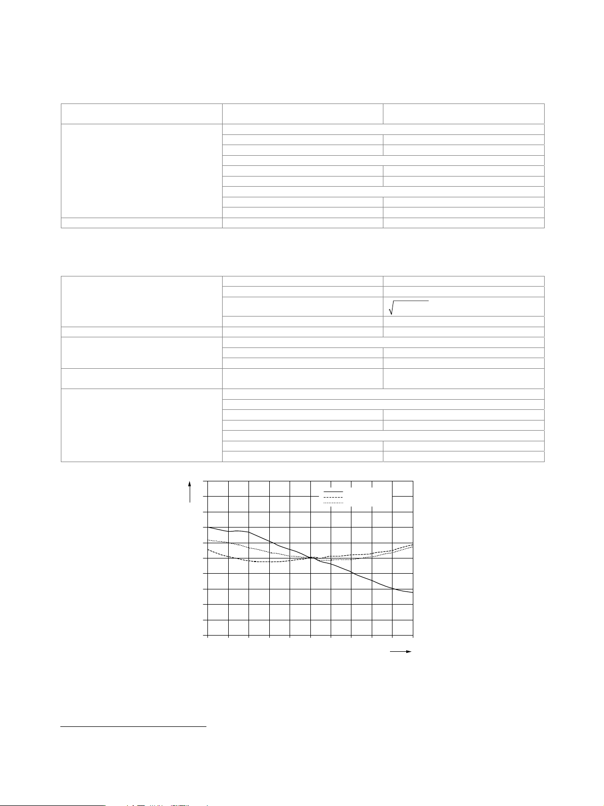
I/Q modulation
I/Q modulator
Operating modes external wideband I/Q,
internal baseband I/Q
I offset, Q offset
setting range −10 % to +10 %
resolution 0.01 %
gain imbalance
setting range −1.0 dB to +1.0 dB
resolution 0.001 dB
quadrature offset
setting range −10° to +10°
I/Q impairments
resolution 0.01°
I/Q swap I and Q signals swapped on/off
External wideband I/Q
This type of modulation is possible only in path A.
input impedance 50
VSWR up to 50 MHz < 1.2
input voltage for full-scale input
q
22
i
+= 0.5 V
VV
I/Q inputs
minimum input voltage for ALC state: on 0.1 V
Modulation frequency range I/Q wideband: on 100 MHz
I/Q wideband: on
up to 50 MHz < 6 dB (typ.)
RF frequency response for entire
instrument in modulation bandwidth
up to 5 MHz < 1.0 dB (typ.)
Carrier leakage without input signal, referenced to
full-scale input
3
<
−55 dBc, < −65 dBc (typ.)
measured with 16QAM, root cosine filter, α = 0.5, symbol rate 10 kHz
RMS value
f 200 MHz < 0.3 %
f > 200 MHz < (0.2 % + 0.1 % × f/GHz)
peak value
f 200 MHz < 0.6 %
Error vector
f > 200 MHz < (0.4 % + 0.2 % × f/GHz)
Delta / dB
5
4
3
2
1
0
–1
– 2
– 3
– 4
– 5
Fre
q
uenc
y
offset from carrier / MHz
– 100 10
0
060– 20– 60 20 40 80– 80 – 40
RF 850 MHz
RF 1900 MHz
RF 2200 MHz
Measured frequency response of external wideband I/Q modulation.
3
Value applies after 1 hour warm-up time and recalibration for 4 hours of operation and temperature variations of less than +5 °C.