SMU_dat-sw-en.pdf - 第18页
Version 08.00, Januar y 2012 18 Rohde & Schwarz R&S ® SMU200A Vector Signal Generator I/Q modulation I/Q modulator Operating modes external wideband I/Q, internal baseband I/Q I offset, Q offset setting range − 1…
Version 08.00, January 2012
Rohde & Schwarz R&S
®
SMU200A Vector Signal Generator 17
Pulse modulation
Operating modes external,
internal (duty cycle approx. 1:1)
On/off ratio > 70 dB
Rise/fall time 10 %/90 % of RF amplitude 1 µs (typ.)
Pulse repetition frequency 0 Hz to 100 kHz
Video crosstalk spectral line of fundamental of 100 kHz
square-wave modulation
< −30 dBc
input level rising 1.7 V, falling 1.1 V (typ.)
input impedance > 10 k
Modulation input
EXT MOD A/B
polarity selectable
Frequency modulation (R&S
®
SMU-B20 or R&S
®
SMU-B22 option)
Operating modes internal, external, internal + external,
AC/DC, normal,
low noise (with R&S
®
SMU-B22 only)
0.3 MHz f 200 MHz rm = 1
200 MHz < f 375 MHz rm = 0.25
375 MHz < f 750 MHz rm = 0.5
750 MHz < f 1500 MHz rm = 1
1500 MHz < f 3000 MHz rm = 2
FM/M range multiplier
f > 3000 MHz rm = 4
FM mode: normal rm × 10 MHz Maximum deviation
FM mode: low noise rm × 100 kHz
Resolution < 200 ppm, min. rm × 0.1 Hz
f
mod
= 10 kHz, deviation half of maximum deviation
internal < (1.5 % of reading + 20 Hz)
Setting uncertainty
external < (2.0 % of reading + 20 Hz)
FM distortion f
mod
= 10 kHz and 1 MHz deviation < 0.1 %
FM mode: normal
10 Hz to 100 kHz < 0.5 dB
10 Hz to 10 MHz < 3 dB
FM mode: low noise
Modulation frequency response
10 Hz to 100 kHz < 3 dB
40 kHz deviation, f
mod
= 1 kHz, f > 5 MHz < 0.1 % Synchronous AM
f > 3 GHz < 0.2 %
Carrier frequency offset at FM < 0.2 % of set deviation
Phase modulation (R&S
®
SMU-B20 or R&S
®
SMU-B22 option)
Operating mode internal, external, internal + external,
AC/DC, high bandwidth,
high deviation,
low noise (with R&S
®
SMU-B22 only)
M mode: high deviation rm × 20.0 rad
M mode: high bandwidth rm × 1.0 rad
Maximum deviation
M mode: low noise rm × 0.25 rad
M mode: high deviation < 200 ppm, min. rm × 20 µrad
M mode: high bandwidth < 0.1 %, min. rm × 20 µrad
Resolution
M mode: low noise < 200 ppm, min. rm × 20 µrad
f
mod
= 10 kHz, deviation half of maximum deviation
internal < (1.5 % of reading + 0.01 rad)
Setting uncertainty
external < (2.0 % of reading + 0.01 rad)
M distortion f
mod
= 10 kHz, half of maximum deviation < 0.2 %, 0.1 % (typ.)
10 Hz to 500 kHz,
M mode: high deviation
< 1 dB
10 Hz to 10 MHz,
M mode: high bandwidth
< 3 dB
Modulation frequency response
10 Hz to 100 kHz, M mode: low noise < 3 dB
Version 08.00, January 2012
18 Rohde & Schwarz R&S
®
SMU200A Vector Signal Generator
I/Q modulation
I/Q modulator
Operating modes external wideband I/Q,
internal baseband I/Q
I offset, Q offset
setting range −10 % to +10 %
resolution 0.01 %
gain imbalance
setting range −1.0 dB to +1.0 dB
resolution 0.001 dB
quadrature offset
setting range −10° to +10°
I/Q impairments
resolution 0.01°
I/Q swap I and Q signals swapped on/off
External wideband I/Q
This type of modulation is possible only in path A.
input impedance 50
VSWR up to 50 MHz < 1.2
input voltage for full-scale input
q
22
i
+= 0.5 V
VV
I/Q inputs
minimum input voltage for ALC state: on 0.1 V
Modulation frequency range I/Q wideband: on 100 MHz
I/Q wideband: on
up to 50 MHz < 6 dB (typ.)
RF frequency response for entire
instrument in modulation bandwidth
up to 5 MHz < 1.0 dB (typ.)
Carrier leakage without input signal, referenced to
full-scale input
3
<
−55 dBc, < −65 dBc (typ.)
measured with 16QAM, root cosine filter, α = 0.5, symbol rate 10 kHz
RMS value
f 200 MHz < 0.3 %
f > 200 MHz < (0.2 % + 0.1 % × f/GHz)
peak value
f 200 MHz < 0.6 %
Error vector
f > 200 MHz < (0.4 % + 0.2 % × f/GHz)
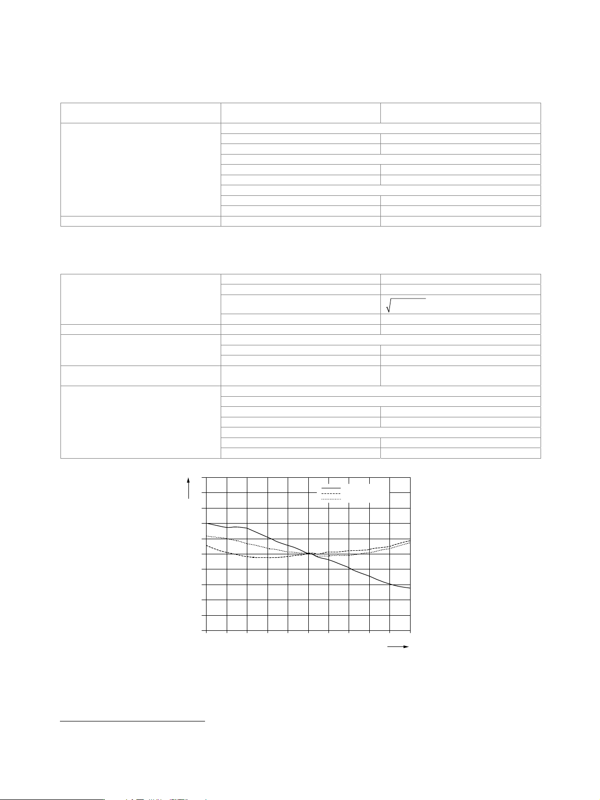
Delta / dB
5
4
3
2
1
0
–1
– 2
– 3
– 4
– 5
Fre
q
uenc
y
offset from carrier / MHz
– 100 10
0
060– 20– 60 20 40 80– 80 – 40
RF 850 MHz
RF 1900 MHz
RF 2200 MHz
Measured frequency response of external wideband I/Q modulation.
3
Value applies after 1 hour warm-up time and recalibration for 4 hours of operation and temperature variations of less than +5 °C.

Version 08.00, January 2012
Rohde & Schwarz R&S
®
SMU200A Vector Signal Generator 19
Internal baseband I/Q (with R&S
®
SMU-B13 option)
The R&S
®
SMU-B13 option converts the internal digital baseband signals of the R&S
®
SMU-B9/-B10/-B11 into analog signals for driving
the I/Q modulator. It also generates the analog I/Q output signals. One or two R&S
®
SMU-B13 can be installed.
The first R&S
®
SMU-B13 drives RF path A, the second RF path B. The I/Q output signals are available either for path A or B.
data rate 100 MHz
resolution 16 bit
D/A converter
sample rate 400 MHz (internal interpolation × 4)
with amplitude, group delay and S
i
correction
bandwidth, roll-off to −0.1 dB 40 MHz
D/A converter interpolation spectra
up to 10 MHz < −80 dBc
Aliasing filter
up to 40 MHz <
−73 dBc
carrier leakage
setting range −10 % to +10 %
resolution 0.01 %
I ≠ Q (imbalance)
setting range −1 dB to +1 dB
resolution 0.001 dB
quadrature offset
setting range −10° to +10°
I/Q impairment
resolution 0.01°
f > 100 MHz, –20 dBm level 10 dBm, I/Q wideband: on, optimize internal I/Q
impairments for RF output: on, optimization mode: high quality
up to 10 MHz < 0.5 dB, 0.1 dB (typ.)
RF frequency response for entire
instrument in modulation bandwidth
up to 40 MHz < 2.0 dB, 0.3 dB (typ.)
up to 10 MHz > 50 dB, 56 dB (typ.) Suppression of image sideband for entire
instrument in modulation bandwidth
3
up to 40 MHz > 40 dB, 50 dB (typ.)
Carrier leakage
3
referenced to full-scale input < −55 dBc, < −65 dBc (typ.)
Additional level uncertainty referenced to
CW
measured at 0 dBm with 16QAM, root
cosine filter,
α = 0.5, 10 kHz symbol rate
< 0.2 dB
I/Q outputs
Output impedance 50
Output voltage EMF (output voltage depends on set
modulation signal)
1 V (V
p
)
Offset EMF < 1 mV
at R
L
= 50
magnitude
up to 10 MHz 0.02 dB (typ.)
up to 40 MHz 0.03 dB (typ.)
nonlinear phase
up to 10 MHz 0.1° (typ.)
Frequency response
4
up to 30 MHz 0.2° (typ.)
at R
L
= 50
magnitude
up to 10 MHz 0.01 dB (typ.)
up to 40 MHz 0.02 dB (typ.)
nonlinear phase
up to 10 MHz 0.1° (typ.)
I/Q balance
4
up to 30 MHz 0.2° (typ.)
at R
L
= 50
SFDR (sine)
up to 2 MHz > 70 dB
up to 20 MHz 60 dB (typ.)
phase noise
10 MHz sine wave at 20 kHz offset −150 dBc (typ.)
wideband noise
Spectral purity
10 MHz sine wave at 1 MHz offset
−155 dBc (typ.)
4
Optimize internal I/Q impairments for RF output switched off.