SMU_dat-sw-en.pdf - 第23页
Version 08.00, Januar y 2012 Rohde & Schwarz R&S ® SMU200A Vector Signal Generator 23 Carrier leakage referenced to full scale < − 55 dBc, < − 65 dBc (typ.) up to 10 MHz 56 dB (t yp.) Suppression of image s…
Version 08.00, January 2012
22 Rohde & Schwarz
R&S
®
SMU200A Vector Signal Generator
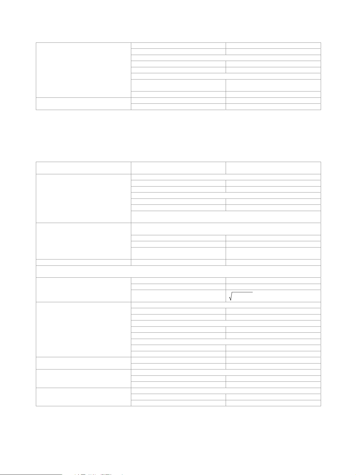
resolution 18 bit
logic format two’s complement
physical signal level
setting range 0 to –60 dBFS
resolution 0.01 dBFS
bandwidth
sample rate = 100 MHz
(no interpolation, user-defined)
40 MHz
I/Q data
sample rate < 100 MHz (interpolation) 0.31 × sample rate
markers 4 Control signals
data valid valid samples marked in data stream
Baseband input (analog/digital) (R&S
®
SMU-B17 option)
At least one R&S
®
SMU-B13 baseband main module and at least one R&S
®
SMU-B9/-B10/-B11 I/Q baseband generator must be
installed. The R&S
®
SMU-B17 option makes it possible to feed external analog or digital signals to the baseband section of the
R&S
®
SMU200A. The frequency of the signals can be shifted, and the signals can be added to the internally generated signal with
settable level ratio. If the R&S
®
SMU200A is equipped with a fading simulator, the input signals can also be faded.
Mode see also simultaneous modulation analog input,
digital input
peak level
setting range –10 dB to 0 dB referenced to full scale
resolution 0.01 dB
crest factor
setting range 0 dB to 30 dB
resolution 0.01 dB
Input level
The adjust level function automatically determines the peak level and crest factor of the
input signal.
The frequency offset can be used to shift the center frequency of the input signal in the
baseband. The restrictions caused by the modulation bandwidth apply.
setting range −40 MHz to +40 MHz
resolution 0.01 Hz
Frequency offset
frequency accuracy < 5 × 10
− 10 × frequency offset +
reference frequency error
I/Q swap I and Q signals swapped on/off
Analog I/Q inputs
All specifications apply to a peak level of 0 dB.
input impedance 50
VSWR up to 30 MHz < 1.1, 1.03 (typ.)
I/Q inputs
input voltage for full-scale input
q
22
i
+= 0.5 V
VV
carrier leakage I, Q
setting range −10 % to +10 %
resolution 0.01 %
I ≠ Q (imbalance)
setting range −3 dB to +3 dB
resolution 0.001 dB
I/Q skew
setting range –1 ns to +1 ns
I/Q impairment
resolution 1 ps
sample rate 100 MHz A/D converter
resolution 14 bit
with amplitude and group delay correction
bandwidth, roll-off to –0.1 dB 30 MHz
Aliasing filter
stopband rejection, f 70 MHz 80 dB (typ.)
I/Q wideband: on, optimize internal I/Q impairments for RF output: on
up to 10 MHz 0.2 dB (typ.)
RF frequency response for entire
instrument in modulation bandwidth
up to 30 MHz 0.4 dB (typ.)

Version 08.00, January 2012
Rohde & Schwarz R&S
®
SMU200A Vector Signal Generator 23
Carrier leakage referenced to full scale <
−55 dBc, < −65 dBc (typ.)
up to 10 MHz 56 dB (typ.) Suppression of image sideband for entire
instrument in modulation bandwidth
up to 30 MHz 50 dB (typ.)
wideband noise, with full-scale DC input
20 MHz f 200 MHz –145 dBc (typ.)
200 MHz < f 1.5 GHz –148 dBc (typ.)
1.5 GHz < f 3 GHz –148 dBc (typ.)
f > 1.5 GHz –145 dBc (typ.)
ACLR with an ideal input signal, 3GPP test model 1, 64 DPCH
level 10.5 dBm PEP, 16.5 dBm PEP with R&S
®
SMU-B31, R&S
®
SMU-B36 options
frequency = 1800 MHz to 2200 MHz
5 MHz offset (baseband gain: 3 dB) 70 dB (typ.)
RF spectral purity
10 MHz offset (baseband gain: 6 dB) 73 dB (typ.)
Digital I/Q inputs
standard in line with Rohde & Schwarz TVR290,
I/Q data and control signals, data and
interface clock
level LVDS
connector 26-pin MDR
Interface
data rate 66 MHz to 100 MHz
source user-defined, digital I/Q in
sample rate 400 Hz to 100 MHz
resolution (user-defined) 0.001 Hz
I/Q sample rate
(max. sample rate depends on interface
data rate)
With source ‘user-defined’, the sample
rate must be entered via the parameter
‘sample rate’, no I/Q data clock being
necessary. With source ‘digital I/Q in’, the
sample rate will be estimated on the basis
of the applied I/Q data clock.
frequency uncertainty (user-defined) < 5 × 10
−
14
resolution 18 bit
logic format two’s complement
bandwidth
sample rate = 100 MHz
(no interpolation, user-defined)
40 MHz
I/Q data
sample rate < 100 MHz (interpolation) 0.31 × sample rate
markers 4 Control signals
data valid valid samples marked in data stream

Version 08.00, January 2012
24 Rohde & Schwarz
R&S
®
SMU200A Vector Signal Generator
I/Q baseband generator (R&S
®
SMU-B9/-B10/-B11 option) – arbitrary
waveform mode
At least one R&S
®
SMU-B13 baseband main module must be installed. One or two R&S
®
SMU-B9/-B10/-B11 options can be installed.
Their I/Q signals can be assigned a frequency offset and/or be added in the digital domain with settable level ratio.
output memory
waveform length with R&S
®
SMU-B9
option
128 sample to 128 Msample in
one-sample steps
waveform length with R&S
®
SMU-B10
option
128 sample to 64 Msample in one-sample
steps
waveform length with R&S
®
SMU-B11
option
128 sample to 16 Msample in one-sample
steps
resolution 16 bit
loading time 10 Msample 15 s
Waveform memory
nonvolatile memory hard disk
number of segments max. 1024 segments
changeover modes GUI, remote control, external trigger
extended trigger modes same segment, next segment, next
segment seamless, sequencer
changeover time at 50 MHz clock rate
(external trigger, without clock change)
5 µs (meas.)
seamless changeover output up to end of current segment,
followed by changeover to next segment
sequencer play list length max. 96
Multisegment waveform
sequencer segment repetitions max. 65535
number of carriers max. 32
total RF bandwidth max. 80 MHz
crest factor modes maximize, minimize, off
signal period modes longest file, shortest file, user (max. 1 s)
single carrier gain –80 dB to 0 dB
single carrier start phase 0° to 360°
Multicarrier waveform
single carrier delay 0 s to 1 s
clock rate 400 Hz to 100 MHz
resolution 0.001 Hz
operating mode internal, external
Clock generation
frequency uncertainty (internal) < 5 × 10
−
14
× clock rate +
uncertainty of reference frequency
The sample rate of the waveform is automatically interpolated to the internal 100 MHz
data rate.
bandwidth
clock rate = 100 MHz (no interpolation),
roll-off to –0.1 dB
40 MHz
Interpolation
clock rate 100 MHz, drop to
−0.1 dB 0.31 × clock rate
The frequency offset can be used to shift the center frequency of the wanted baseband
signal. The restrictions caused by the modulation bandwidth apply.
range −40 MHz to +40 MHz
resolution 0.01 Hz
Frequency offset
frequency uncertainty < 5 × 10
− 10 × frequency offset +
reference frequency error