SMU_dat-sw-en.pdf - 第25页
Version 08.00, Januar y 2012 Rohde & Schwarz R&S ® SMU200A Vector Signal Generator 25 In internal clock mode, a trigger event restarts the clock generation. The clock phase is then synchronous with the trigger ( …

Version 08.00, January 2012
24 Rohde & Schwarz
R&S
®
SMU200A Vector Signal Generator
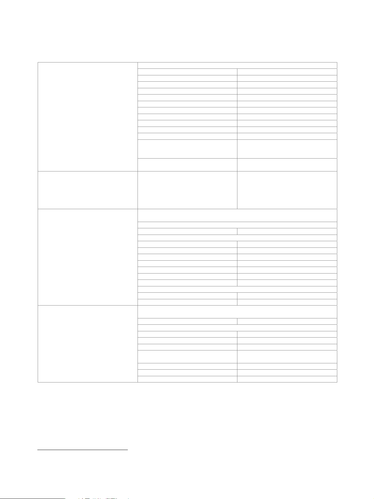
I/Q baseband generator (R&S
®
SMU-B9/-B10/-B11 option) – arbitrary
waveform mode
At least one R&S
®
SMU-B13 baseband main module must be installed. One or two R&S
®
SMU-B9/-B10/-B11 options can be installed.
Their I/Q signals can be assigned a frequency offset and/or be added in the digital domain with settable level ratio.
output memory
waveform length with R&S
®
SMU-B9
option
128 sample to 128 Msample in
one-sample steps
waveform length with R&S
®
SMU-B10
option
128 sample to 64 Msample in one-sample
steps
waveform length with R&S
®
SMU-B11
option
128 sample to 16 Msample in one-sample
steps
resolution 16 bit
loading time 10 Msample 15 s
Waveform memory
nonvolatile memory hard disk
number of segments max. 1024 segments
changeover modes GUI, remote control, external trigger
extended trigger modes same segment, next segment, next
segment seamless, sequencer
changeover time at 50 MHz clock rate
(external trigger, without clock change)
5 µs (meas.)
seamless changeover output up to end of current segment,
followed by changeover to next segment
sequencer play list length max. 96
Multisegment waveform
sequencer segment repetitions max. 65535
number of carriers max. 32
total RF bandwidth max. 80 MHz
crest factor modes maximize, minimize, off
signal period modes longest file, shortest file, user (max. 1 s)
single carrier gain –80 dB to 0 dB
single carrier start phase 0° to 360°
Multicarrier waveform
single carrier delay 0 s to 1 s
clock rate 400 Hz to 100 MHz
resolution 0.001 Hz
operating mode internal, external
Clock generation
frequency uncertainty (internal) < 5 × 10
−
14
× clock rate +
uncertainty of reference frequency
The sample rate of the waveform is automatically interpolated to the internal 100 MHz
data rate.
bandwidth
clock rate = 100 MHz (no interpolation),
roll-off to –0.1 dB
40 MHz
Interpolation
clock rate 100 MHz, drop to
−0.1 dB 0.31 × clock rate
The frequency offset can be used to shift the center frequency of the wanted baseband
signal. The restrictions caused by the modulation bandwidth apply.
range −40 MHz to +40 MHz
resolution 0.01 Hz
Frequency offset
frequency uncertainty < 5 × 10
− 10 × frequency offset +
reference frequency error

Version 08.00, January 2012
Rohde & Schwarz R&S
®
SMU200A Vector Signal Generator 25
In internal clock mode, a trigger event restarts the clock generation. The clock phase is
then synchronous with the trigger (with a certain timing uncertainty).
In external clock mode, the trigger event is synchronized to the symbol clock.
operating mode internal, external
modes auto, retrig, armed auto, armed retrig
setting uncertainty for clock phase related
to trigger in internal clock mode
< 18 ns
external trigger delay
setting range 0 sample to (2
16
– 1) sample
resolution
internal clock mode 0.01 sample
external clock mode 1 sample
setting uncertainty < 5 ns
external trigger inhibit
setting range 0 sample to (2
26
– 1) sample
resolution 1 sample
external trigger pulse width > 15 ns
Triggering
external trigger frequency < 0.02 × sample rate
number 4
level LVTTL
operating modes unchanged, restart, pulse, pattern, ratio
marker delay
setting range 0 sample to (waveform length − 1) sample
setting range without recalculation 0 sample to 2000 sample
resolution of setting 0.001 sample
Marker outputs
setting uncertainty < 10 ns
Operation with R&S
®
WinIQSIM2™: As of version 1.00, the software supports I/Q data download and control of the
R&S
®
SMU-B9/-B10/-B11 options.
Version 08.00, January 2012
26 Rohde & Schwarz
R&S
®
SMU200A Vector Signal Generator
I/Q baseband generator (R&S
®
SMU-B9/-B10/-B11 option) – realtime operation
At least one R&S
®
SMU-B13 baseband main module must be installed. One or two R&S
®
SMU-B9/-B10/-B11 options can be installed.
Their I/Q signals can be assigned a frequency offset and/or be added in the digital domain with settable level ratio.
ASK
modulation index 0 % to 100 %
resolution 0.1 %
FSK 2FSK, 4FSK, MSK
deviation 0.1 to 1.5 × f
sym
maximum 10 MHz
resolution < 0.1 Hz
setting uncertainty < 0.5 %
variable FSK 4FSK, 8FSK, 16FSK
deviations –1.5 × f
sym
to +1.5 × f
sym
maximum 10 MHz
resolution < 0.1 Hz
PSK BPSK, QPSK, QPSK 45° offset, OQPSK,
π/4-QPSK, π/2-DBPSK, π/4-DQPSK,
π/8-D8PSK, 8PSK, 8PSK EDGE
Types of modulation
QAM 16QAM, 32QAM, 64QAM, 256QAM,
1024QAM
Coding Not all coding methods can be used with
every type of modulation.
off, differential, diff. phase,
diff. + Gray, Gray, GSM, NADC, PDC,
PHS, TETRA, APCO25 (PSK), PWT,
TFTS, INMARSAT, VDL, EDGE,
APCO25(FSK), ICO, CDMA2000
®
6
,
WCDMA
Any filter can be used with any type of modulation. The bandwidth of the modulation
signal is max. 25 MHz; the signal is clipped if the bandwidth is exceeded.
cosine, root cosine
filter parameter α 0.05 to 1.00
Gaussian
filter parameter B × T 0.15 to 2.50
cdmaOne, cdmaOne + equalizer
cdmaOne 705 kHz,
cdmaOne 705 kHz + equalizer
CDMA2000
®
3x
APCO25 C4FM
rectangular
split phase
filter parameter B × T 0.15 to 2.5
Baseband filter
resolution of filter parameter 0.01
If an external clock is used, the applied data rate may deviate from the set clock rate by
±2 %. The external clock can be used for internal and external data.
operating mode internal, external
setting range
ASK, PSK, QAM 400 Hz to 25 MHz
FSK 400 Hz to 15 MHz
resolution 0.001 Hz
frequency uncertainty (internal)
< 5 × 10
–14
× symbol rate + reference
frequency uncertainty
external clock symbol, K × symbol, bit clock
clock divider K 1 to 64
Symbol rate
external clock rate max. 100 MHz
6
CDMA2000
®
is a registered trademark of the Telecommunications Industry Association (TIA - USA).