SMU_dat-sw-en.pdf - 第27页
Version 08.00, Januar y 2012 Rohde & Schwarz R&S ® SMU200A Vector Signal Generator 27 The frequency offset can be used to shift t he center frequency of the modulation signal in the baseband. The restrictions cau…
Version 08.00, January 2012
26 Rohde & Schwarz
R&S
®
SMU200A Vector Signal Generator
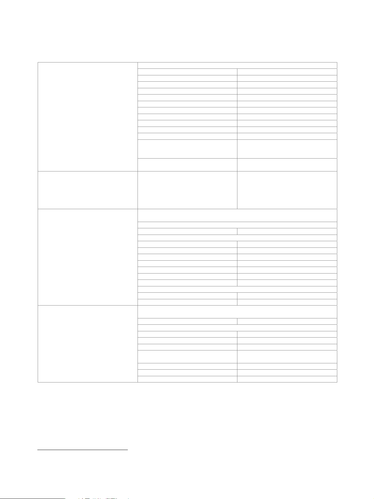
I/Q baseband generator (R&S
®
SMU-B9/-B10/-B11 option) – realtime operation
At least one R&S
®
SMU-B13 baseband main module must be installed. One or two R&S
®
SMU-B9/-B10/-B11 options can be installed.
Their I/Q signals can be assigned a frequency offset and/or be added in the digital domain with settable level ratio.
ASK
modulation index 0 % to 100 %
resolution 0.1 %
FSK 2FSK, 4FSK, MSK
deviation 0.1 to 1.5 × f
sym
maximum 10 MHz
resolution < 0.1 Hz
setting uncertainty < 0.5 %
variable FSK 4FSK, 8FSK, 16FSK
deviations –1.5 × f
sym
to +1.5 × f
sym
maximum 10 MHz
resolution < 0.1 Hz
PSK BPSK, QPSK, QPSK 45° offset, OQPSK,
π/4-QPSK, π/2-DBPSK, π/4-DQPSK,
π/8-D8PSK, 8PSK, 8PSK EDGE
Types of modulation
QAM 16QAM, 32QAM, 64QAM, 256QAM,
1024QAM
Coding Not all coding methods can be used with
every type of modulation.
off, differential, diff. phase,
diff. + Gray, Gray, GSM, NADC, PDC,
PHS, TETRA, APCO25 (PSK), PWT,
TFTS, INMARSAT, VDL, EDGE,
APCO25(FSK), ICO, CDMA2000
®
6
,
WCDMA
Any filter can be used with any type of modulation. The bandwidth of the modulation
signal is max. 25 MHz; the signal is clipped if the bandwidth is exceeded.
cosine, root cosine
filter parameter α 0.05 to 1.00
Gaussian
filter parameter B × T 0.15 to 2.50
cdmaOne, cdmaOne + equalizer
cdmaOne 705 kHz,
cdmaOne 705 kHz + equalizer
CDMA2000
®
3x
APCO25 C4FM
rectangular
split phase
filter parameter B × T 0.15 to 2.5
Baseband filter
resolution of filter parameter 0.01
If an external clock is used, the applied data rate may deviate from the set clock rate by
±2 %. The external clock can be used for internal and external data.
operating mode internal, external
setting range
ASK, PSK, QAM 400 Hz to 25 MHz
FSK 400 Hz to 15 MHz
resolution 0.001 Hz
frequency uncertainty (internal)
< 5 × 10
–14
× symbol rate + reference
frequency uncertainty
external clock symbol, K × symbol, bit clock
clock divider K 1 to 64
Symbol rate
external clock rate max. 100 MHz
6
CDMA2000
®
is a registered trademark of the Telecommunications Industry Association (TIA - USA).
Version 08.00, January 2012
Rohde & Schwarz R&S
®
SMU200A Vector Signal Generator 27
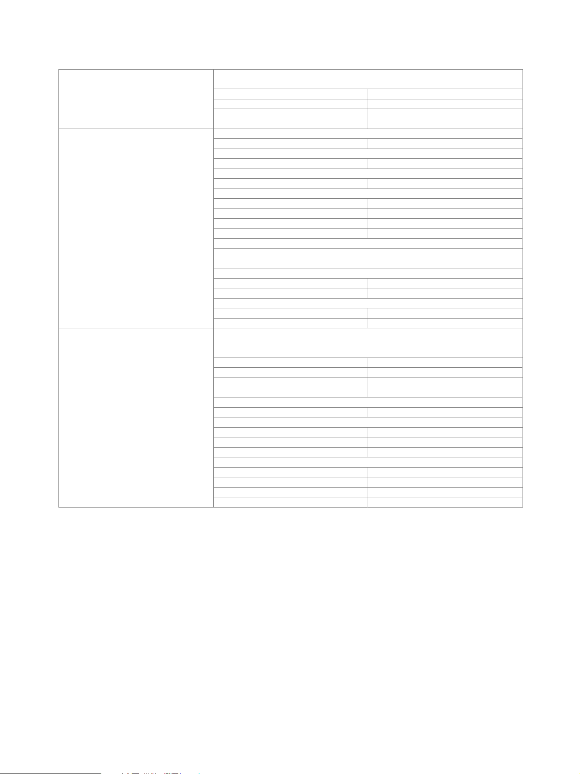
The frequency offset can be used to shift the center frequency of the modulation signal
in the baseband. The restrictions caused by the modulation bandwidth apply.
setting range −40 MHz to +40 MHz
resolution 0.01 Hz
Frequency offset
frequency uncertainty < 5 × 10
− 10 × frequency offset +
reference frequency error
internal
All 0, All 1
PRBS
sequence length 9, 11, 15, 16, 20, 21, 23
pattern
length 1 bit to 64 bit
data lists
R&S
®
SMU-B9 output memory 8 bit to 4 Gbit
R&S
®
SMU-B10 output memory 8 bit to 2 Gbit
R&S
®
SMU-B11 output memory 8 bit to 512 Mbit
nonvolatile memory hard disk
external
In the case of serial transmission, the symbol strobe marks the LSB of the symbol, and
the maximum symbol rate is limited by the data rate of the interface.
serial
word width 1 bit to 10 bit
bit rate max. 60 MHz
parallel
word width 1 bit to 10 bit
Data sources
symbol rate max. 25 MHz
In internal clock mode, a trigger event restarts the clock generation. The clock phase is
then synchronous with the trigger (with a certain timing uncertainty).
In external clock mode, the trigger event is synchronized to the symbol clock.
operating mode internal, external
modes auto, retrig, armed auto, armed retrig
setting uncertainty for clock phase related
to trigger in internal clock mode
< 18 ns
external trigger delay
setting range 0 sample to (2
16
– 1) sample
resolution
internal clock mode 0.01 sample
external clock mode 1 sample
setting uncertainty < 5 ns
external trigger inhibit
setting range 0 sample to (2
26
– 1) sample
resolution 1 sample
external trigger pulse width > 15 ns
Triggering
external trigger frequency < 0.02 × sample rate
Version 08.00, January 2012
28 Rohde & Schwarz
R&S
®
SMU200A Vector Signal Generator
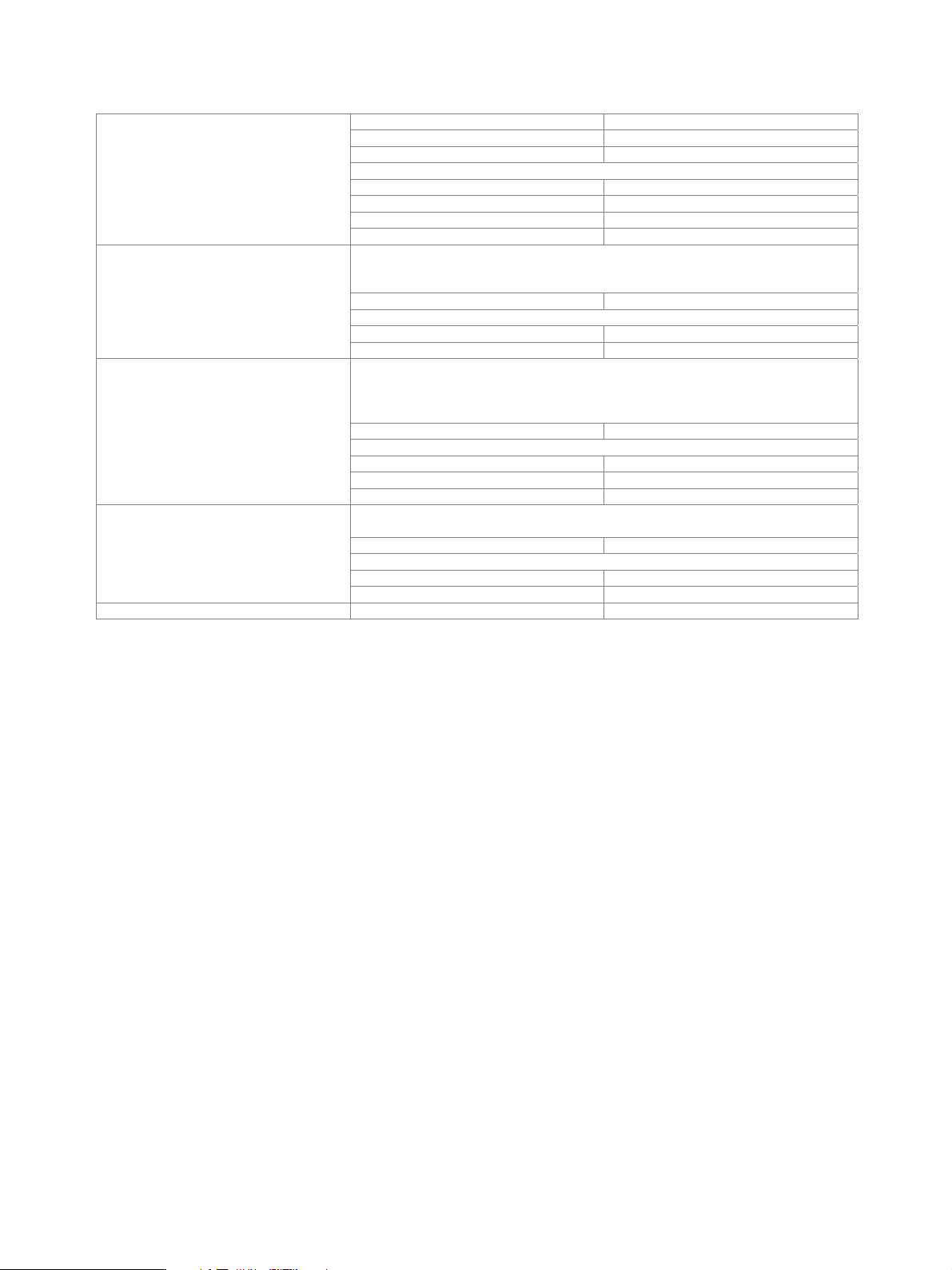
number 4
level LVTTL
operating modes control list, restart, pulse, pattern, ratio
marker delay (in sample)
setting range 0 to 2
24
– 1
setting range without recalculation 0 to 2000
resolution of setting 0.001
Marker outputs
setting uncertainty < 10 ns
Internal or external via LEVATT input. The signal switches between nominal and
reduced level (without edge shaping). If an internal LEVATT signal is used, the
connector is used as an output.
setting range 0 dB to 60 dB
additional level error in case of reduction
up to 30 dB < 1 dB
Level reduction
up to 50 dB < 3 dB
Internal or external via BURST input. The signal triggers the beginning of a power
ramp. The positive edge starts power ramping from blank to full level, the negative edge
ramping in the opposite direction from full level to blanking. If an internal BURST GATE
signal is applied, the connector is used as an output.
operating range max. 5 MHz
rise/fall time
setting range 0.5 symbol to 16 symbol
resolution 0.1 symbol
Burst
ramp shape cosine, linear
The input impedance and trigger threshold can be set separately for the trigger and the
clock/data inputs.
input impedance 1 k, 50
trigger threshold
setting range 0.00 V to 2.50 V
Trigger/clock/data inputs
resolution 0.01 V
Clock/data outputs level LVTTL