SMU_dat-sw-en.pdf - 第36页
Version 08.00, Januar y 2012 36 Rohde & Schwarz R&S ® SMU200A Vector Signal Generator Fading and noise Fading simulator (R&S ® SMU-B14 option) a nd fading simulator extension (R&S ® SMU-B15 option) The R&…

Version 08.00, January 2012
Rohde & Schwarz R&S
®
SMU200A Vector Signal Generator 35
Digital standards with R&S
®
WinIQSIM2™
(for the R&S
®
SMU-B9/-B10/-B11 ARB)
At least one I/Q baseband generator (R&S
®
SMU-B9/-B10/-B11 options) must be installed. If two I/Q baseband generators are installed
and two waveforms of the same standard (e.g. GSM/EDGE) are to be output simultaneously, two corresponding software options must
also be installed (in this case R&S
®
SMU-K240). If only one R&S
®
SMU-K240 is installed and GSM/EDGE waveforms are played in one
I/Q baseband generator, the other I/Q baseband generator is disabled for GSM/EDGE waveforms. However, a software option is not
tied to a specific I/Q baseband generator.
R&S
®
WinIQSIM2™ requires an external PC.
GSM/EDGE R&S
®
SMU-K240 option
EDGE Evolution R&S
®
SMU-K241 option
3GPP FDD R&S
®
SMU-K242 option
3GPP FDD enhanced BS/MS tests including HSDPA R&S
®
SMU-K243 option
GPS R&S
®
SMU-K244 option
3GPP FDD HSUPA R&S
®
SMU-K245 option
CDMA2000
®
R&S
®
SMU-K246 option
1xEV-DO R&S
®
SMU-K247 option
IEEE 802.11a/b/g R&S
®
SMU-K248 option
IEEE 802.16 WiMAX™ R&S
®
SMU-K249 option
TD-SCDMA (3GPP TDD LCR) R&S
®
SMU-K250 option
TD-SCDMA (3GPP TDD LCR) enhanced BS/MS tests including HSDPA R&S
®
SMU-K251 option
DVB-H/DVB-T R&S
®
SMU-K252 option
DAB/T-DMB R&S
®
SMU-K253 option
IEEE 802.11n R&S
®
SMU-K254 option
EUTRA/LTE R&S
®
SMU-K255 option
HSPA+ R&S
®
SMU-K259 option
Bluetooth
®
EDR R&S
®
SMU-K260 option
Multicarrier CW signal generation R&S
®
SMU-K261 option
Additive white Gaussian noise (AWGN) R&S
®
SMU-K262 option
TETRA Release 2 R&S
®
SMU-K268 option
EUTRA/LTE Release 9 and enhanced features R&S
®
SMU-K284 option
EUTRA/LTE Release 10 (LTE-Advanced) R&S
®
SMU-K285 option
IEEE 802.11ac R&S
®
SMU-K286 option
The options are described in the R&S
®
WinIQSIM2™ data sheet (PD 5213.7460.22).

Version 08.00, January 2012
36 Rohde & Schwarz
R&S
®
SMU200A Vector Signal Generator
Fading and noise
Fading simulator (R&S
®
SMU-B14 option) and fading simulator extension
(R&S
®
SMU-B15 option)
The R&S
®
SMU-B9/-B10/-B11 or R&S
®
SMU-B17 option is required to generate input signals for the fading simulator.
All frequency and time settings are coupled to the internal reference frequency.
with R&S
®
SMU-B14 1 Number of signal paths
with R&S
®
SMU-B14 and R&S
®
SMU-B15 1 or 2
only possible with R&S
®
SMU-B14 and R&S
®
SMU-B15
input both signal paths split or combined
Signal routing
output split, one signal path only or sum of both
signal paths
Number of fading paths depending on options and signal routing, see table on next page
setting range 0 dB to 50 dB
resolution 0.01 dB
Fading path loss
accuracy < 0.01 dB
setting range 0 ms to 2.56 ms
resolution 10 ns
Fading path delay
with R&S
®
SMU-K71 option 0.01 ns
max. 4 per signal path Delay groups
permitted delay differences within one
group
< 40 µs
at f = 1 GHz 0 km/h to 1725 km/h Speed range
accuracy < 0.128 %
setting range 0 Hz to 1600 Hz Doppler frequency
accuracy < 0.1 %
standard auto Restart
with R&S
®
SMU-B9/-B10/-B11 options
installed
auto, internal from baseband A or B,
external
Total insertion loss automatic or user-definable, with clipping
indicator
0 dB to 18 dB
fading paths in signal path A pairwise with fading paths in signal path B
correlation coefficient
setting range 0 % to 100 %
resolution 5 %
correlation phase
setting range 0° to 360°
Correlation
resolution 1°
Fading profiles
Rayleigh pseudo-noise interval > 93 h
frequency ratio (–1 to +1) × current Doppler frequency Pure Doppler
resolution 0.01 × current Doppler frequency
combination of Rayleigh and pure Doppler Rician
power ratio –30 dB to +30 dB
standard deviation 0 dB to 12 dB
resolution 1 dB
Lognormal
local constant at f = 1 GHz 12 m to 200 m
path loss 0 dB to 50 dB
phase 0° to 360°
Static, constant phase
resolution 1°
Version 08.00, January 2012
Rohde & Schwarz R&S
®
SMU200A Vector Signal Generator 37
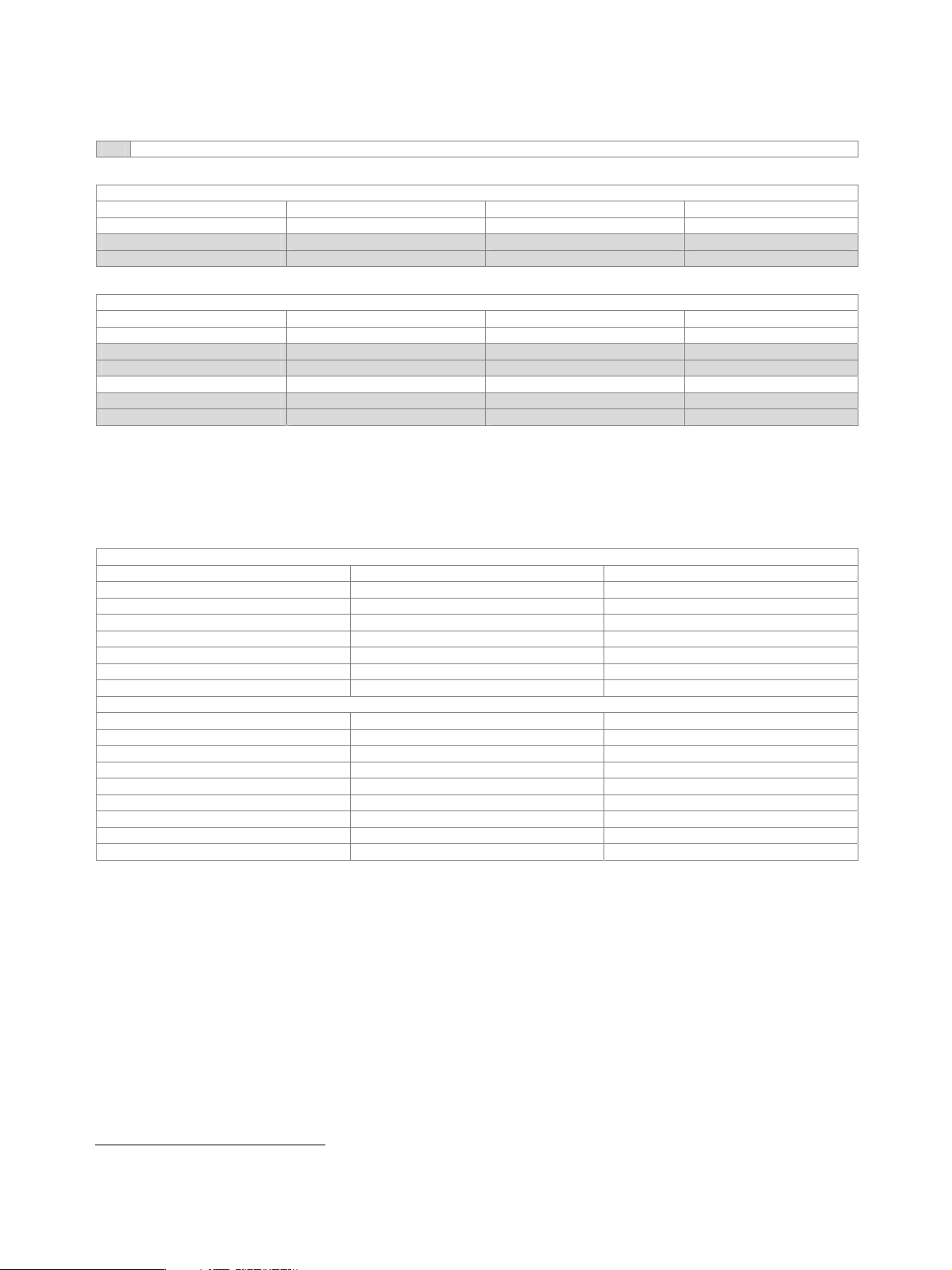
Number of fading paths, RF bandwidth and timing resolution
With R&S
®
SMU-K71 only
With R&S
®
SMU-B14
Signal paths Fading paths RF bandwidth Timing resolution
1 20 80 MHz 10 ns
1 12 30 MHz 0.01 ns
1 8 50 MHz 0.01 ns
With R&S
®
SMU-B14 and R&S
®
SMU-B15
Signal paths Fading paths RF bandwidth Timing resolution
1 40 80 MHz 10 ns
1 24 30 MHz 0.01 ns
1 16 50 MHz 0.01 ns
2 20 80 MHz 10 ns
2 12 30 MHz 0.01 ns
2 8 50 MHz 0.01 ns
Dynamic fading and enhanced resolution (R&S
®
SMU-K71 option)
At least one R&S
®
SMU-B14 fading simulator must be installed. If both the R&S
®
SMU-B14 and the R&S
®
SMU-B15 are installed (signal
paths A and B), dynamic fading and enhanced resolution can be used either on signal path A or B with one R&S
®
SMU-K71 option. For
dynamic fading and enhanced resolution to be used on signal paths A and B simultaneously, two R&S
®
SMU-K71 must be installed.
Moving delay mode
System bandwidth 50 MHz
Number of fading paths 2 per signal path
Fading profiles none
Basic delay in steps of 10 ns 0 ms to 2.56 ms
Delay variation peak to peak 0.3 µs to 40 µs
Variation period peak to peak 10 s to 500 s
Variation speed peak to peak 0 µs/s to 500 µs/s
Delay step size < 10 ps
Birth-death mode
System bandwidth 50 MHz
Number of fading paths 2 per signal path
Fading profiles pure Doppler
Delay range 0 µs to 40 µs
Delay grid 0 µs to 20 µs
16
Positions 3 to 50
16
Hopping dwell 100 ms to 5 s
Start offset separately settable for each signal path 1 ms to 200 ms
Delay resolution 10 ns
16
The maximum delay range of 40 µs cannot be exceeded.