SMU_dat-sw-en.pdf - 第39页
Version 08.00, Januar y 2012 Rohde & Schwarz R&S ® SMU200A Vector Signal Generator 39 1x4 MIMO Number of signal paths with two R&S ® SMU200A, both with R&S ® SMU-B14 and R&S ® SMU-B15 4 Signal routing…
Version 08.00, January 2012
38 Rohde & Schwarz
R&S
®
SMU200A Vector Signal Generator
Extended statistic functions (R&S
®
SMU-K72 option)
At least one R&S
®
SMU-B14 fading simulator must be installed. If both the R&S
®
SMU-B14 and the R&S
®
SMU-B15 are installed (signal
paths A and B), extended statistic functions can be used either on signal path A or B with one R&S
®
SMU-K72 option. For extended
statistic functions to be used on signal paths A and B simultaneously, two R&S
®
SMU-K72 must be installed.
Fading profiles
Gauss I, Gauss II sum of two Gaussian distributions in line with DAB standard
Gauss DAB 1, Gauss DAB 2 Gaussian distribution, shifted in frequency in line with DAB standard
WiMAX™ Doppler rounded Doppler PSD model in line with IEEE 802.16a-03-01
WiMAX™ Rice like WiMAX™ Doppler plus pure Doppler in line with IEEE 802.16a-03-01
SUI1 to SUI6 in line with IEEE 802.16a-03-01 Predefined settings
DAB-RA, DAB-TU, DAB-SFN in line with EN 50248-2001
MIMO fading (R&S
®
SMU-K74 option)
The R&S
®
SMU-K74 option allows four fading channels to be simulated as is required for 1x2, 2x1 and 2x2 MIMO receiver tests.
Both the R&S
®
SMU-B14 and the R&S
®
SMU-B15 options must be installed (signal paths A and B) and two baseband sources
(R&S
®
SMU-B9, -B10 or -B11) must be present. By combining two instruments, it is possible to simulate receiver test scenarios for 1x3,
1x4, 2x3, 2x4, 3x1, 4x1, 3x2 and 4x2 MIMO.
standard, 80 MHz RF bandwidth,
10 ns timing resolution
10
with R&S
®
SMU-K71 option, 50 MHz RF
bandwidth, 0.01 ns timing resolution
4
Number of fading paths in each channel
with R&S
®
SMU-K71 option, 30 MHz RF
bandwidth, 0.01 ns timing resolution
6
Steering matrix The steering matrix can be set by setting the diagonal elements of the correlation
matrix.
The correlation between corresponding fading paths of the signal paths can be set in a
correlation matrix. For each fading path index, an individual matrix can be set.
correlation coefficient
setting range 0 % to 100 %
resolution 1 %
correlation phase
setting range 0° to 360°
Correlation
resolution 1°
Correlation matrix setting individually or with Kronecker assumption
(RX and TX antenna correlation with
automatic calculation of matrix)
Matrix representation (real, imaginary) or (magnitude, phase)
Start seed settable
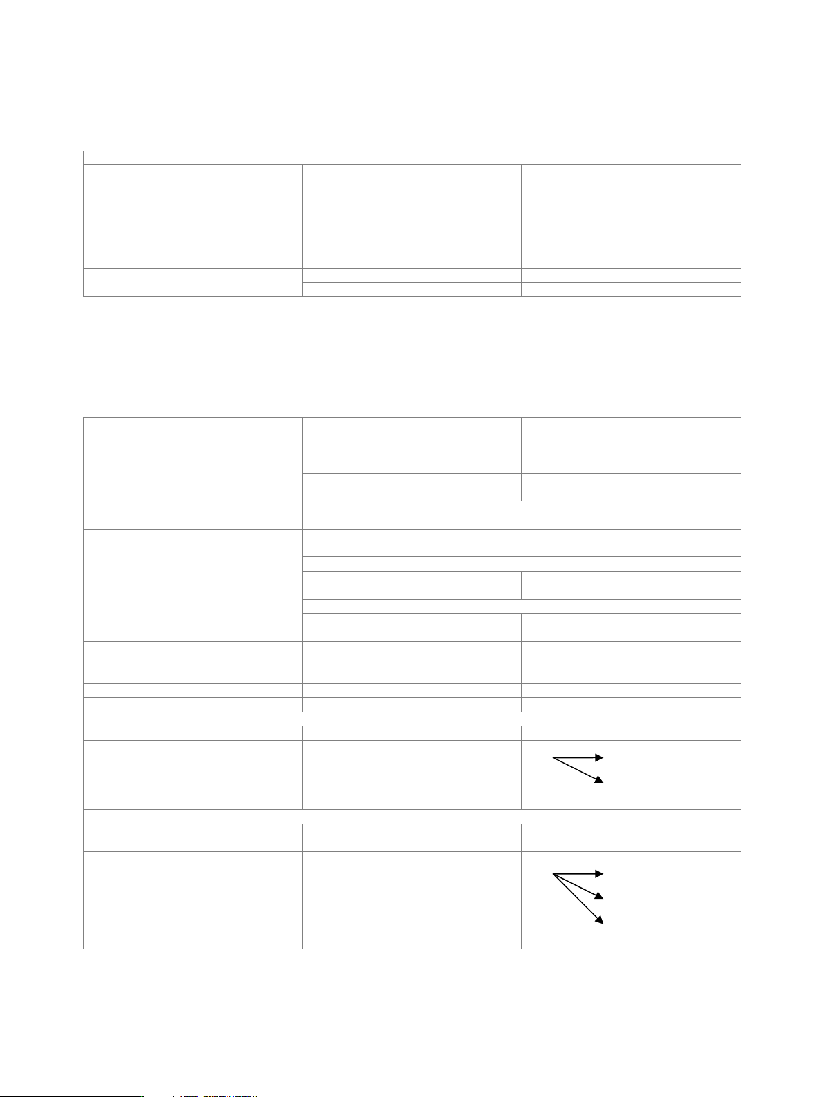
1x2 MIMO
Number of signal paths with R&S
®
SMU-B14 and R&S
®
SMU-B15 2
Signal routing 1x2 MIMO, simulating fading channels
between one TX and two RX antennas
A A
B
1x3 MIMO
Number of signal paths
with two R&S
®
SMU200A, both with
R&S
®
SMU-B14 and R&S
®
SMU-B15
3
Signal routing 1x3 MIMO, simulating fading channels
between one TX and three RX antennas
A A
B
C
Version 08.00, January 2012
Rohde & Schwarz R&S
®
SMU200A Vector Signal Generator 39
1x4 MIMO
Number of signal paths with two R&S
®
SMU200A, both with
R&S
®
SMU-B14 and R&S
®
SMU-B15
4
Signal routing 1x4 MIMO, simulating fading channels
between one TX and four RX antennas
A
A
B
C
D
2x1 MIMO
Number of signal paths with R&S
®
SMU-B14 and R&S
®
SMU-B15 2
Signal routing 2x1 MIMO, simulating fading channels
between two TX and one RX antennas
A A
B
3x1 MIMO
Number of signal paths with two R&S
®
SMU200A, both with
R&S
®
SMU-B14 and R&S
®
SMU-B15;
external signal combiner required
(either baseband or RF combiner)
3
Signal routing 3x1 MIMO, simulating fading channels
between three TX and one RX antennas
A A
B
C
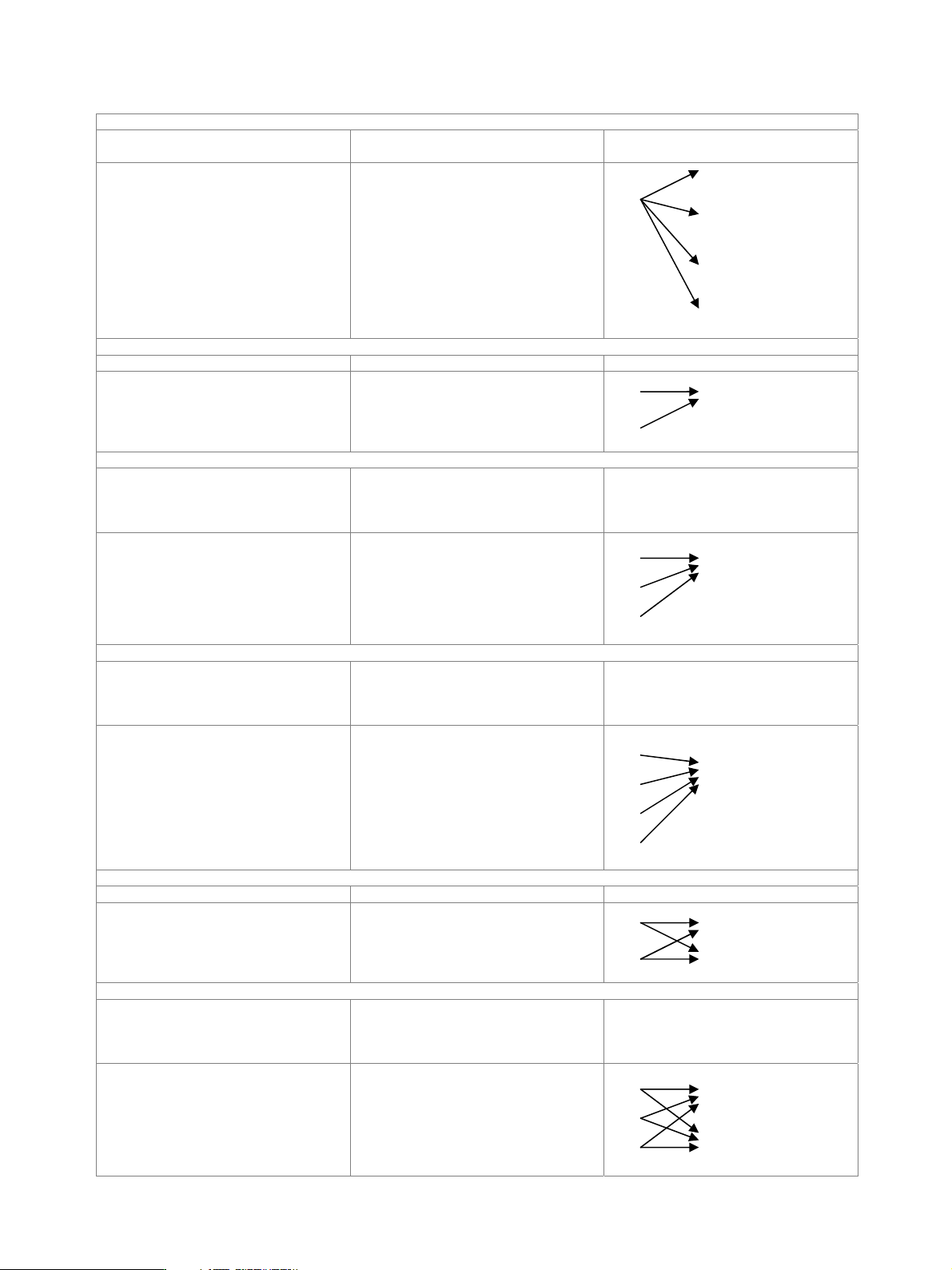
4x1 MIMO
Number of signal paths with two R&S
®
SMU200A, both with
R&S
®
SMU-B14 and R&S
®
SMU-B15;
external signal combiner required
(either baseband or RF combiner)
4
Signal routing 4x1 MIMO, simulating fading channels
between four TX and one RX antennas
A
A
B
C
D
2x2 MIMO
Number of signal paths with R&S
®
SMU-B14 and R&S
®
SMU-B15 4
Signal routing 2x2 MIMO, simulating fading channels
between two TX and two RX antennas
A A
B B
3x2 MIMO
Number of signal paths with two R&S
®
SMU200A, both with
R&S
®
SMU-B14 and R&S
®
SMU-B15;
external signal combiner required
(either baseband or RF combiner)
6
Signal routing 3x2 MIMO, simulating fading channels
between three TX and two RX antennas
A A
B
C B
Version 08.00, January 2012
40 Rohde & Schwarz
R&S
®
SMU200A Vector Signal Generator
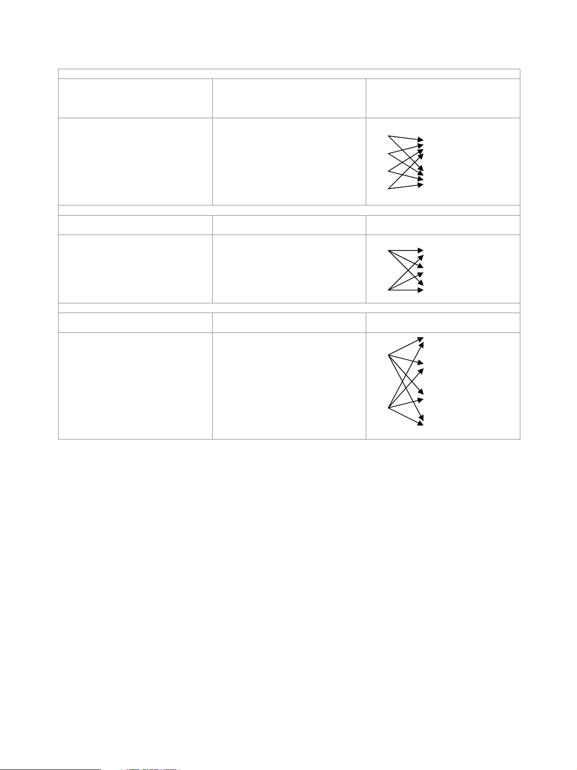
4x2 MIMO
Number of signal paths with two R&S
®
SMU200A, both with
R&S
®
SMU-B14 and R&S
®
SMU-B15;
external signal combiner required
(either baseband or RF combiner)
8
Signal routing 4x2 MIMO, simulating fading channels
between four TX and two RX antennas
A
B A
C B
D
2x3 MIMO
Number of signal paths with two R&S
®
SMU200A, both with
R&S
®
SMU-B14 and R&S
®
SMU-B15
6
Signal routing 2x3 MIMO, simulating fading channels
between two TX and three RX antennas
A A
B
B C
2x4 MIMO
Number of signal paths with two R&S
®
SMU200A, both with
R&S
®
SMU-B14 and R&S
®
SMU-B15
8
Signal routing 2x4 MIMO, simulating fading channels
between two TX and four RX antennas
A
A
B
C
B
D