SMU_dat-sw-en.pdf - 第42页
Version 08.00, Januar y 2012 42 Rohde & Schwarz R&S ® SMU200A Vector Signal Generator Other options BER measurement (R&S ® SMU-K80 option) The data supplied by the DUT is compared with a reference pseudo-rand…
Version 08.00, January 2012
Rohde & Schwarz R&S
®
SMU200A Vector Signal Generator 41
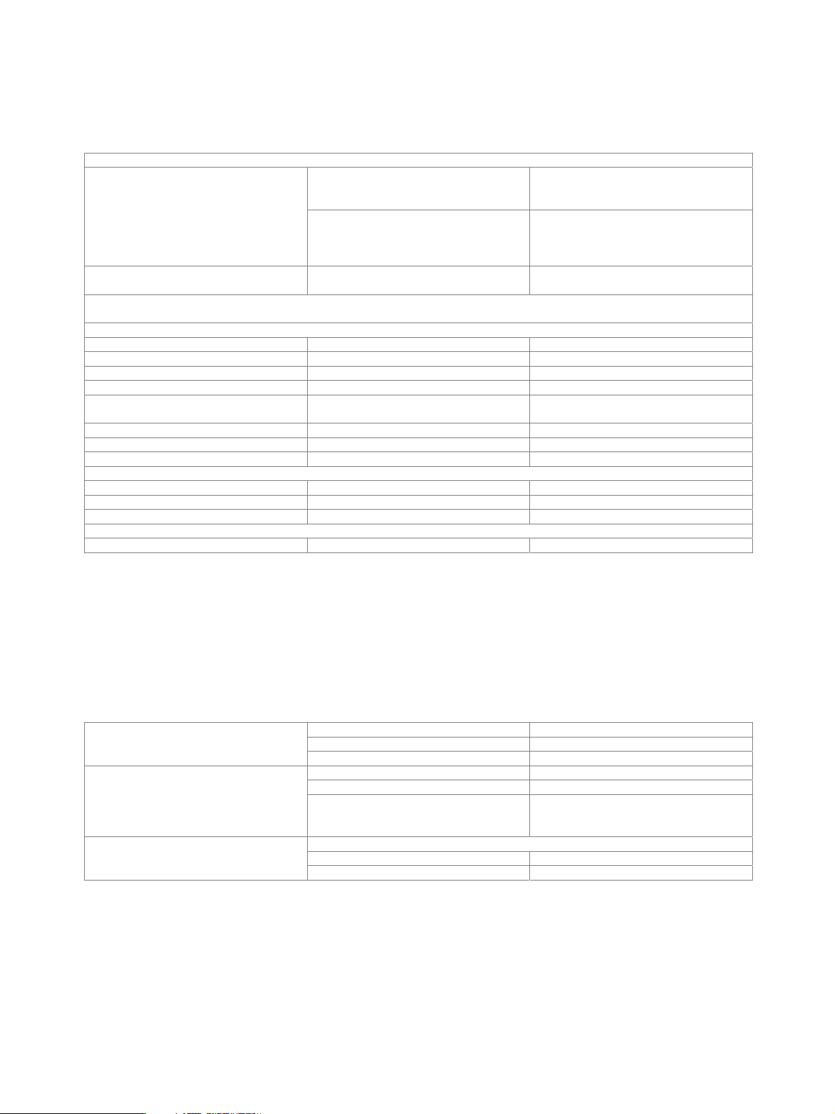
Dynamic scenario simulation (R&S
®
SMU-K77 option)
At least one R&S
®
SMU-B14 fading simulator must be installed. If both the R&S
®
SMU-B14 and the R&S
®
SMU-B15 are installed (signal
paths A and B), dynamic scenario simulation can be used either on signal path A or B with one R&S
®
SMU-K77 option. For dynamic
scenario simulation to be used on signal paths A and B simultaneously, two R&S
®
SMU-K77 must be installed.
Scenarios
ship to ship simulation of the signal transmission from
one object to another, each moving on a
straight line of definable direction
Predefined
tower to aircraft simulation of the signal transmission
between a tower and an aircraft; the
aircraft takes off, flies a circuit and lands
again
User-defined simulation of two moving objects trajectories and type of object (and their
limits) are fully customizable
A trajectory viewer visualizes the generated trajectories and displays the position of the objects in realtime. The display shows an x-y
and x-z view. The viewer is available for both predefined and user-defined scenarios.
Basic figures
System bandwidth 50 MHz
Number of fading paths 1 LOS per signal path
Fading profiles pure Doppler
Delay resolution 0.5 ns
Propagation delay 0 s to 160 s (corresponds to a range
difference of 0 km to 47.967 km)
Minimum position dwell time 0.1 ms
Maximum Doppler frequency shift 3 kHz
Number of simulated objects 2
Import interfaces
Trajectory description file proprietary file format (see manual) waypoints (ENU, geodetic), velocity, time
TPA file proprietary file format (see manual) time, propagation delay, attenuation
Ephemeris file AGI STK file format position (Cartesian), time, velocity
Export interfaces
Ephemeris file AGI STK file format position (Cartesian), time, velocity
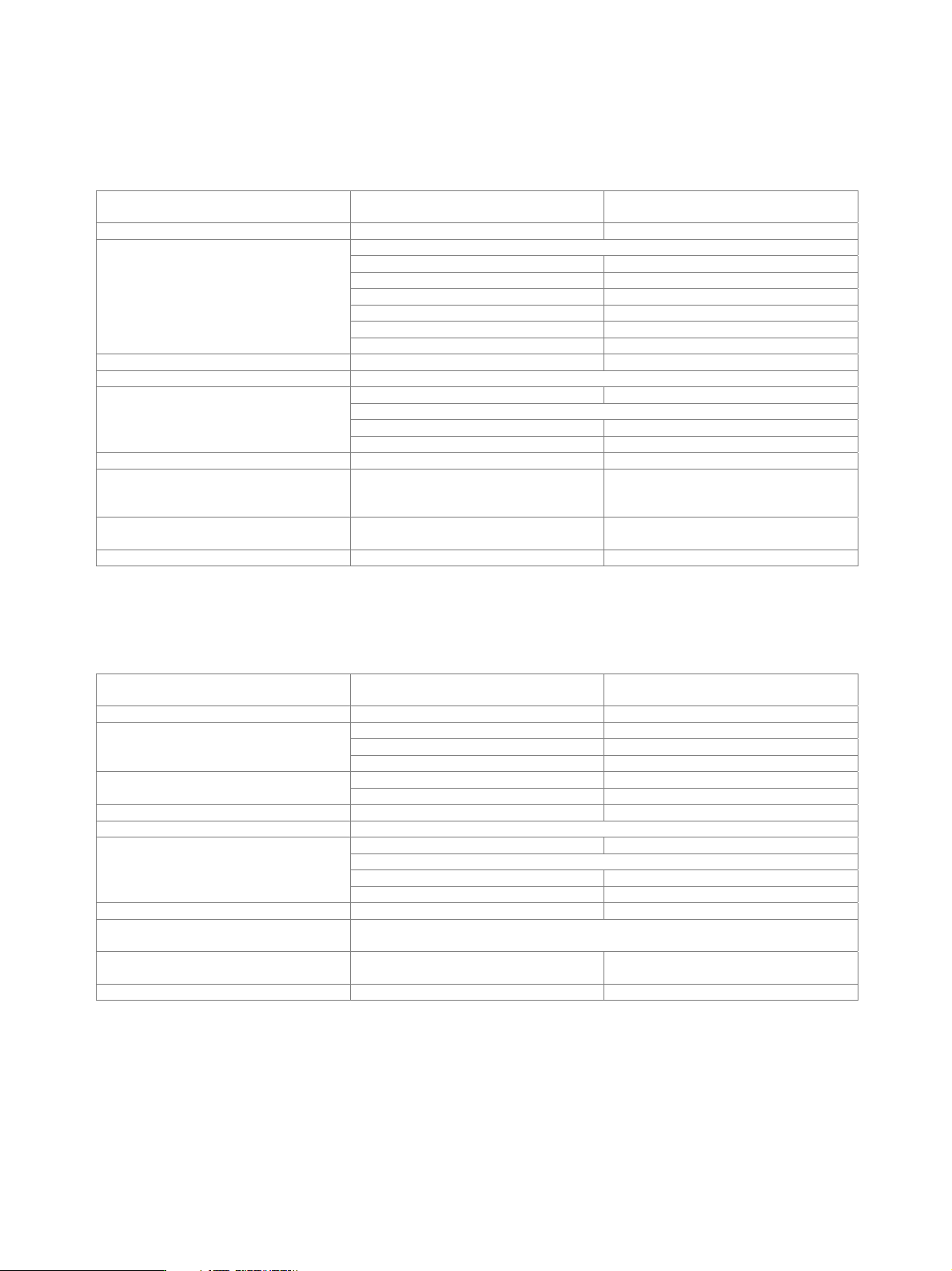
Additive white Gaussian noise (AWGN, R&S
®
SMU-K62 option)
At least one R&S
®
SMU-B13 baseband main module must be installed. If two R&S
®
SMU-B13 are installed (paths A and B), AWGN can
be generated either on path A or B with one R&S
®
SMU-K62 option. For AWGN to be generated on paths A and B simultaneously, two
R&S
®
SMU-K62 must be installed.
Addition of an AWGN signal of settable bandwidth and settable C/N ratio or E
b
/N
0
to a wanted signal. If the noise generator is used,
a frequency offset cannot be added to the wanted signal.
distribution density Gaussian, statistical, separate for I and Q
crest factor > 18 dB
Noise
periodicity > 48 h
setting range −30 dB to +30 dB
resolution 0.1 dB
C/N, E
b
/N
0
uncertainty for system bandwidth = symbol
rate, –24 dB < C/N < 30 dB and
crest factor < 12 dB
< 0.1 dB
bandwidth for determining noise power
range 1 kHz to 80 MHz
System bandwidth
resolution 100 Hz
Version 08.00, January 2012
42 Rohde & Schwarz
R&S
®
SMU200A Vector Signal Generator
Other options
BER measurement (R&S
®
SMU-K80 option)
The data supplied by the DUT is compared with a reference pseudo-random bit sequence.
Clock supplied by DUT; a clock pulse is required
for each valid bit
Clock rate 100 Hz to 60 MHz
PRBS
sequence length 9, 11, 15, 16, 20, 21, 23
pattern ignore off, All 0, All 1
data enable external
modes off, high, low
restart external
Data
modes on/off
Synchronization time 28 clock cycles
Interface 9-pin D-Sub connector, D-Sub/BNC cable supplied with option
input impedance 1 k, 50
trigger threshold
setting range 0.00 V to 2.50 V
Clock, data, enable and restart inputs
resolution 0.01 V
Polarity data, clock, data enable normal, inverted
Measurement time selectable by means of maximum number
of data bits or bit errors (max. 2
31
bit
each), continuous measurement
Measurement result if selected number of data bits or bit errors
is attained
BER in ppm, % or decade values
Status displays not synchronized, no clock, no data
BLER measurement (R&S
®
SMU-K80 option)
In BLER measurement mode, arbitrary data can be supplied by the DUT. A signal marking the block’s CRC has to be provided on the
data enable connector of the BER/BLER option.
Clock supplied by DUT; a clock pulse is required
for each valid bit
Clock rate 100 Hz to 60 MHz
input data arbitrary
data enable (marking the block’s CRC) external
Data
modes high, low
CRC type CCITT CRC16 (x
16
+ x
12
+ x
5
+ 1) CRC
CRC bit order MSB first, LSB first
Synchronization time 1 block
Interface 9-pin D-Sub connector, D-Sub/BNC cable supplied with option
input impedance 1 k, 50
trigger threshold
setting range 0 V to 2.50 V
Clock, data and enable inputs
resolution 0.01 V
Polarity data, clock, data enable normal, inverted
Measurement time selectable by means of maximum number of received blocks or errors (max. 2
31
blocks
each), continuous measurement
Measurement result if selected number of received blocks or
errors is attained
BLER in ppm, % or decade values
Status displays not synchronized, no clock, no data

Version 08.00, January 2012
Rohde & Schwarz R&S
®
SMU200A Vector Signal Generator 43
General data
Remote control
Systems IEC/IEEE bus, IEC 60625 (IEEE 488)
Ethernet
Command set SCPI 1999.5
Connector
IEC/IEEE 24-contact Amphenol
Ethernet Western
IEC/IEEE bus address 0 to 30
Interface functions IEC: SH1, AH1, T6, L4, SR1, RL1, PP1,
DC1, DT1, C0
Operating data
input voltage range, AC, nominal 100 V to 240 V
AC supply frequency 47 Hz to 63 Hz
input current 5.0 A to 1.6 A
Power supply
power factor correction in line with EN 61000-3-2
in line with EN 55011 class B, EN 61326 EMC
with activated digital I/Q output in line with EMC directive of
EU (2004/108/EC), applied standard:
EN 61326 (immunity for industrial
environment; class A emissions)
17
Immunity to interfering field strength up to 10 V/m
operating temperature range +5 °C to +45 °C,
in line with EN 60068-2-1, EN 60068-2-2
storage temperature range −20 °C to +60 °C
Environmental conditions
climatic resistance
+40 °C/90 % rel. humidity,
in line with EN 60068-2-3
Mechanical resistance
sinusoidal 5 Hz to 150 Hz, max. 2 g at 55 Hz,
55 Hz to 150 Hz, 0.5 g const.,
in line with EN 60068-2-6
Vibration
random 10 Hz to 300 Hz,
acceleration 1.2 g (RMS),
in line with EN 60068-2-64
Shock 40 g shock spectrum,
in line with EN 60068-2-27, MIL-STD-810E
Electrical safety in line with EN 61010-1
Dimensions W × H × D 435 mm × 192 mm × 460 mm
(17.1 in × 7.6 in × 18.1 in)
Weight if fully equipped 25 kg (55.1 lb)
Recommended calibration interval 3 years
License information
The firmware of this device contains open source software. Details and license agreements can be found in release notes and
operating manual.
17
The instrument complies with the emission requirements stipulated by EN 55011 class A. This means that the instrument is suitable for use in industrial
environments. In line with EN 61000-6-4, operation in residential, commercial and business areas or in small-size companies is not covered. The
instrument may not be operated in residential, commercial and business areas or in small-size companies, unless additional measures are taken to
ensure that EN 610000-6-3 is complied with.