SMU_dat-sw-en.pdf - 第43页
Version 08.00, Januar y 2012 Rohde & Schwarz R&S ® SMU200A Vector Signal Generator 43 General dat a Remote control Systems IEC/IEEE bus, IEC 60625 (IEEE 488) Ethernet Command set SCPI 1999.5 Connector IEC/IEEE 24…
Version 08.00, January 2012
42 Rohde & Schwarz
R&S
®
SMU200A Vector Signal Generator
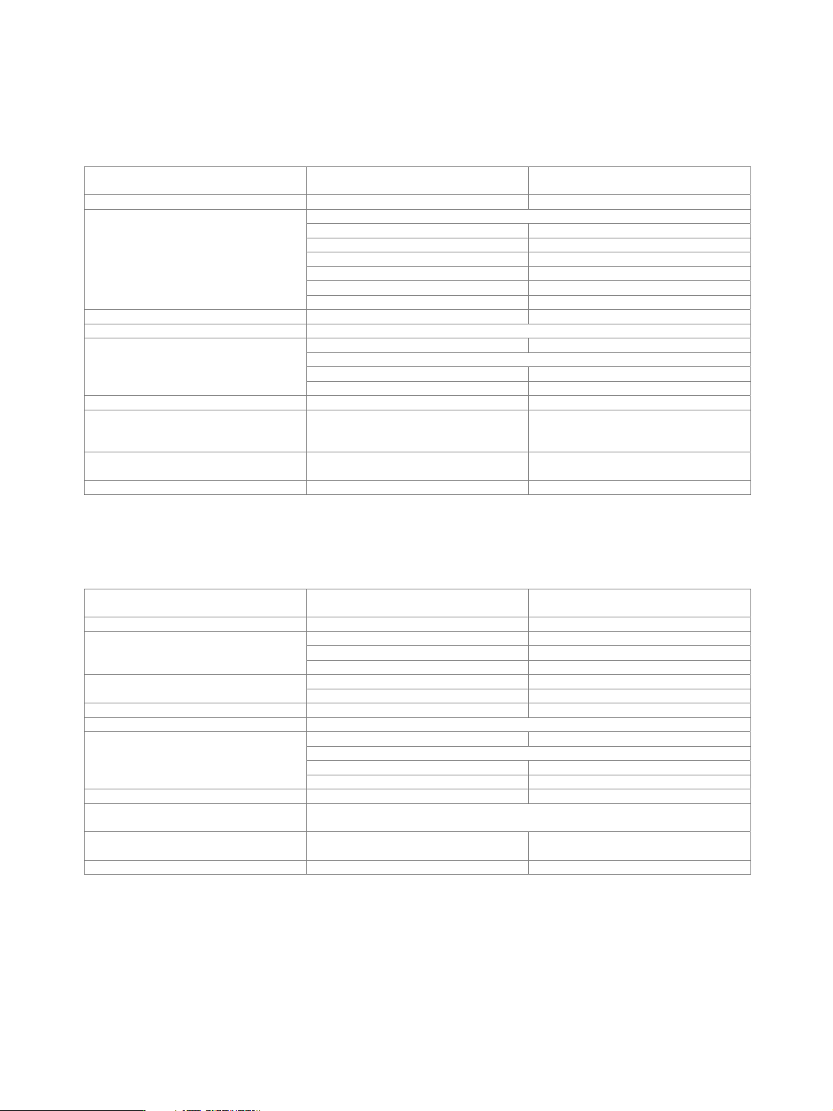
Other options
BER measurement (R&S
®
SMU-K80 option)
The data supplied by the DUT is compared with a reference pseudo-random bit sequence.
Clock supplied by DUT; a clock pulse is required
for each valid bit
Clock rate 100 Hz to 60 MHz
PRBS
sequence length 9, 11, 15, 16, 20, 21, 23
pattern ignore off, All 0, All 1
data enable external
modes off, high, low
restart external
Data
modes on/off
Synchronization time 28 clock cycles
Interface 9-pin D-Sub connector, D-Sub/BNC cable supplied with option
input impedance 1 k, 50
trigger threshold
setting range 0.00 V to 2.50 V
Clock, data, enable and restart inputs
resolution 0.01 V
Polarity data, clock, data enable normal, inverted
Measurement time selectable by means of maximum number
of data bits or bit errors (max. 2
31
bit
each), continuous measurement
Measurement result if selected number of data bits or bit errors
is attained
BER in ppm, % or decade values
Status displays not synchronized, no clock, no data
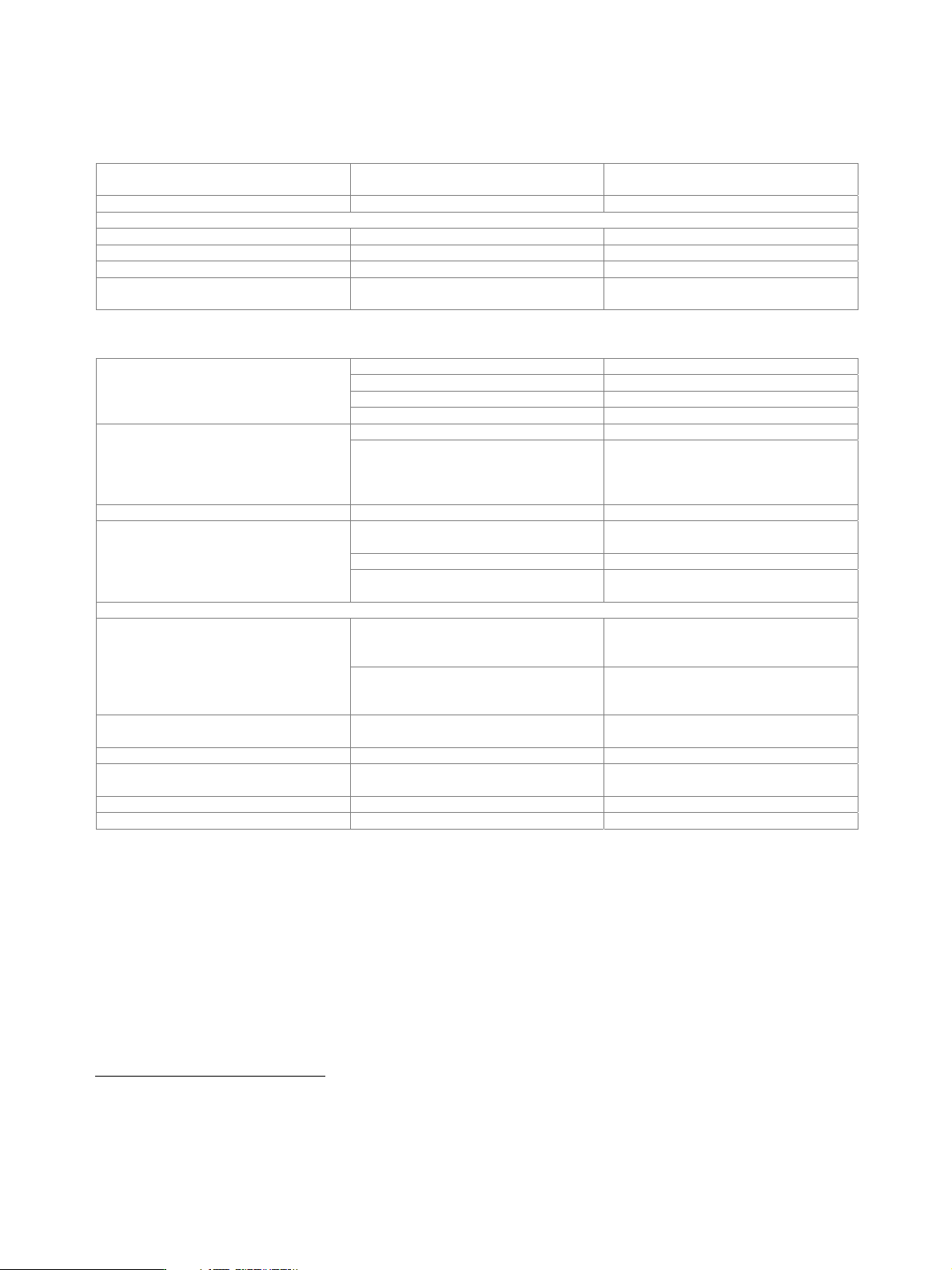
BLER measurement (R&S
®
SMU-K80 option)
In BLER measurement mode, arbitrary data can be supplied by the DUT. A signal marking the block’s CRC has to be provided on the
data enable connector of the BER/BLER option.
Clock supplied by DUT; a clock pulse is required
for each valid bit
Clock rate 100 Hz to 60 MHz
input data arbitrary
data enable (marking the block’s CRC) external
Data
modes high, low
CRC type CCITT CRC16 (x
16
+ x
12
+ x
5
+ 1) CRC
CRC bit order MSB first, LSB first
Synchronization time 1 block
Interface 9-pin D-Sub connector, D-Sub/BNC cable supplied with option
input impedance 1 k, 50
trigger threshold
setting range 0 V to 2.50 V
Clock, data and enable inputs
resolution 0.01 V
Polarity data, clock, data enable normal, inverted
Measurement time selectable by means of maximum number of received blocks or errors (max. 2
31
blocks
each), continuous measurement
Measurement result if selected number of received blocks or
errors is attained
BLER in ppm, % or decade values
Status displays not synchronized, no clock, no data
Version 08.00, January 2012
Rohde & Schwarz R&S
®
SMU200A Vector Signal Generator 43
General data
Remote control
Systems IEC/IEEE bus, IEC 60625 (IEEE 488)
Ethernet
Command set SCPI 1999.5
Connector
IEC/IEEE 24-contact Amphenol
Ethernet Western
IEC/IEEE bus address 0 to 30
Interface functions IEC: SH1, AH1, T6, L4, SR1, RL1, PP1,
DC1, DT1, C0
Operating data
input voltage range, AC, nominal 100 V to 240 V
AC supply frequency 47 Hz to 63 Hz
input current 5.0 A to 1.6 A
Power supply
power factor correction in line with EN 61000-3-2
in line with EN 55011 class B, EN 61326 EMC
with activated digital I/Q output in line with EMC directive of
EU (2004/108/EC), applied standard:
EN 61326 (immunity for industrial
environment; class A emissions)
17
Immunity to interfering field strength up to 10 V/m
operating temperature range +5 °C to +45 °C,
in line with EN 60068-2-1, EN 60068-2-2
storage temperature range −20 °C to +60 °C
Environmental conditions
climatic resistance
+40 °C/90 % rel. humidity,
in line with EN 60068-2-3
Mechanical resistance
sinusoidal 5 Hz to 150 Hz, max. 2 g at 55 Hz,
55 Hz to 150 Hz, 0.5 g const.,
in line with EN 60068-2-6
Vibration
random 10 Hz to 300 Hz,
acceleration 1.2 g (RMS),
in line with EN 60068-2-64
Shock 40 g shock spectrum,
in line with EN 60068-2-27, MIL-STD-810E
Electrical safety in line with EN 61010-1
Dimensions W × H × D 435 mm × 192 mm × 460 mm
(17.1 in × 7.6 in × 18.1 in)
Weight if fully equipped 25 kg (55.1 lb)
Recommended calibration interval 3 years
License information
The firmware of this device contains open source software. Details and license agreements can be found in release notes and
operating manual.
17
The instrument complies with the emission requirements stipulated by EN 55011 class A. This means that the instrument is suitable for use in industrial
environments. In line with EN 61000-6-4, operation in residential, commercial and business areas or in small-size companies is not covered. The
instrument may not be operated in residential, commercial and business areas or in small-size companies, unless additional measures are taken to
ensure that EN 610000-6-3 is complied with.
Version 08.00, January 2012
44 Rohde & Schwarz
R&S
®
SMU200A Vector Signal Generator
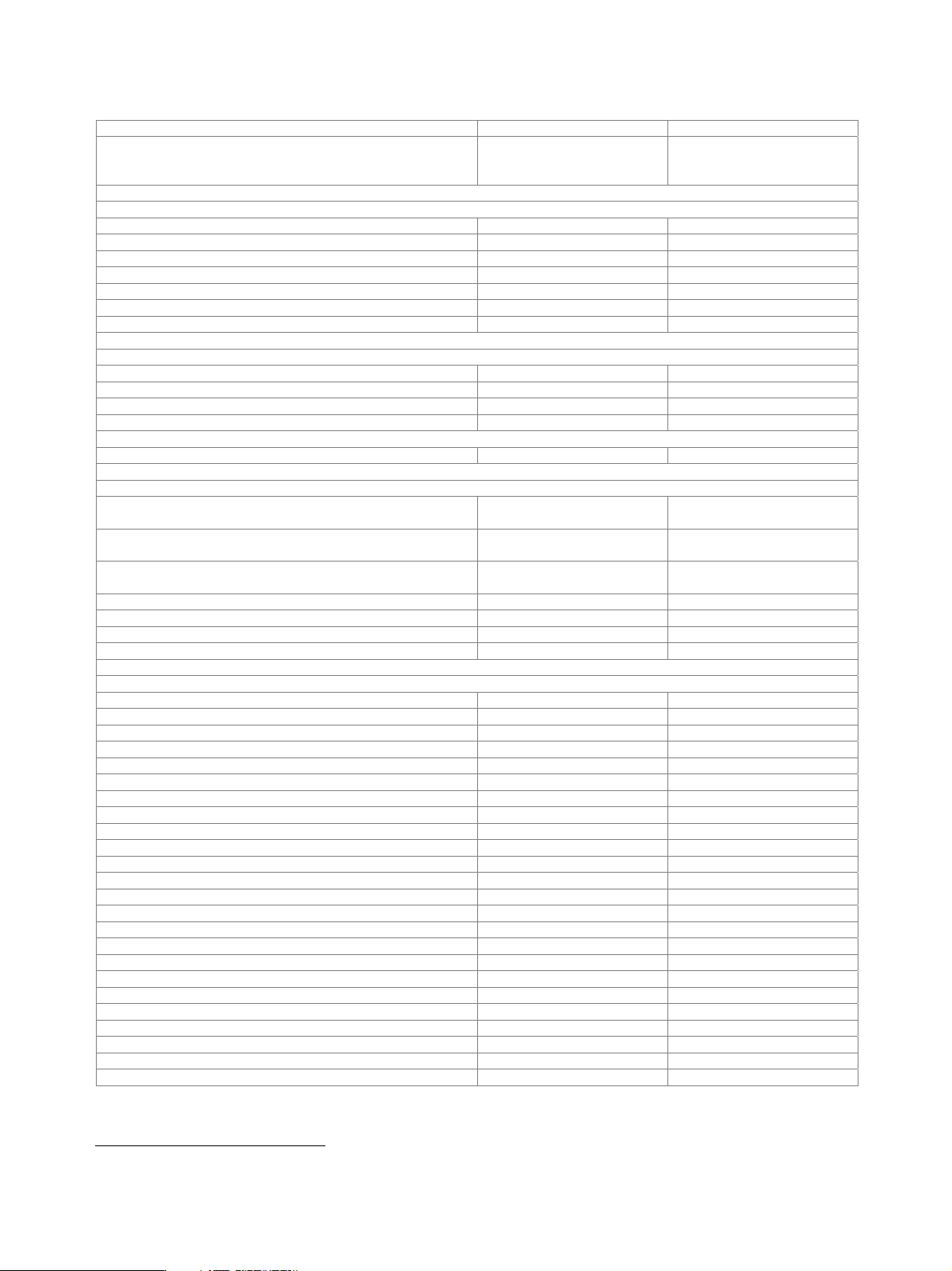
Ordering information
Designation Type Order No.
Vector Signal Generator
18
including power cable, quick start guide and CD-ROM
(with operating and service manual)
R&S
®
SMU200A 1141.2005.02
Options
RF Path A
100 kHz to 2.2 GHz R&S
®
SMU-B102 1141.8503.02
100 kHz to 3 GHz R&S
®
SMU-B103 1141.8603.02
100 kHz to 4 GHz R&S
®
SMU-B104 1141.8703.02
100 kHz to 6 GHz R&S
®
SMU-B106 1141.8803.02
FM/M Modulator R&S
®
SMU-B20 1142.0006.02
FM/M Modulator and Enhanced Phase Noise Performance R&S
®
SMU-B22 1160.5006.02
High-Power Output R&S
®
SMU-B31 1159.8011.04
RF Path B
100 kHz to 2.2 GHz R&S
®
SMU-B202 1141.9400.02
100 kHz to 3 GHz R&S
®
SMU-B203 1141.9500.02
High-Power Output R&S
®
SMU-B36 1160.1000.04
Additional RF options
Phase Coherence R&S
®
SMU-B90 1409.8604.02
Baseband
Baseband Generator with ARB (128 Msample) and
Digital Modulation (realtime)
R&S
®
SMU-B9 1161.0766.02
Baseband Generator with ARB (64 Msample) and
Digital Modulation (realtime)
R&S
®
SMU-B10 1141.7007.02
Baseband Generator with ARB (16 Msample) and
Digital Modulation (realtime)
R&S
®
SMU-B11 1159.8411.02
Baseband Main Module R&S
®
SMU-B13 1141.8003.04
Differential I/Q Output R&S
®
SMU-B16 1161.0066.02
Baseband Input (analog/digital) R&S
®
SMU-B17 1142.2880.02
Digital Baseband Output R&S
®
SMU-B18 1159.6954.02
Digital standards
GSM/EDGE R&S
®
SMU-K40 1160.7609.02
EDGE Evolution R&S
®
SMU-K41 1408.7810.02
3GPP FDD R&S
®
SMU-K42 1160.7909.02
3GPP Enhanced BS/MS Tests incl. HSDPA R&S
®
SMU-K43 1160.9660.02
GPS R&S
®
SMU-K44 1161.0566.02
3GPP FDD HSUPA R&S
®
SMU-K45 1161.0666.02
CDMA2000
®
R&S
®
SMU-K46 1160.9876.02
1xEV-DO R&S
®
SMU-K47 1408.7410.02
IEEE 802.11 (a/b/g) R&S
®
SMU-K48 1161.0266.02
IEEE 802.16 R&S
®
SMU-K49 1161.0366.02
TD-SCDMA R&S
®
SMU-K50 1161.0966.02
TD-SCDMA Enhanced BS/MS Tests R&S
®
SMU-K51 1161.1062.02
DVB-H R&S
®
SMU-K52 1408.7010.02
DAB/T-DMB R&S
®
SMU-K53 1400.6209.02
IEEE 802.11n R&S
®
SMU-K54 1408.7562.02
EUTRA/LTE R&S
®
SMU-K55 1408.7310.02
XM Radio R&S
®
SMU-K56 1161.1162.02
FM Stereo Modulation R&S
®
SMU-K57 1400.6250.02
Sirius Radio R&S
®
SMU-K58 1408.7910.02
3GPP FDD HSPA+ R&S
®
SMU-K59 1415.0053.02
Bluetooth
®
EDR R&S
®
SMU-K60 1408.7962.02
Multicarrier CW Signal Generation R&S
®
SMU-K61 1160.8505.02
Assisted GPS R&S
®
SMU-K65 1415.0053.02
TETRA Release 2 R&S
®
SMU-K68 1408.8217.02
18
The base unit can only be ordered with an R&S
®
SMU-B10x frequency option.