SMU_dat-sw-en.pdf - 第6页
Version 08.00, Januar y 2012 6 Rohde & Schwarz R&S ® SMU200A Vector Signal Generator Frequency and enhancement options Frequency options One of the following frequency opt ions must be installed in RF path A: R&a…

Version 08.00, January 2012
Rohde & Schwarz R&S
®
SMU200A Vector Signal Generator 5
Key features
Two signal generators in one
• Frequency options from 100 kHz to 2.2/3/4/6 GHz for the first RF path
• Optional second RF path up to 2.2 GHz or 3 GHz
• Up to two complete baseband paths
• Lossless combination of baseband signals in the digital domain (e.g. for testing multistandard base stations)
Intuitive operation
• Color display with 800 × 600 pixel (SVGA format)
• Intuitive user interface with graphical display of signal flow (block diagram)
• Graphical display of baseband signals through built-in transient recorder
• Context-sensitive help system
Outstanding signal quality
• I/Q modulator with 200 MHz RF bandwidth
• Very low SSB phase noise of –135 dBc (typ.) (f = 1 GHz, 20 kHz carrier offset, 1 Hz measurement bandwidth), –139 dBc (typ.)
with the enhanced phase noise performance option
• Wideband noise of –153 dBc (typ.) (CW, f = 1 GHz, > 10 MHz carrier offset, 1 Hz measurement bandwidth)
• Excellent ACLR performance of +70 dB (typ.) with 3GPP FDD (test model 1, 64 DPCH)
• Very high level repeatability of 0.05 dB
• High output power of up to +19 dBm (PEP), overrange +26 dBm
• Option for phase-coherent RF outputs
• High-stability reference oscillator as standard
Unrivaled flexibility
• 2x2 MIMO with realtime fading possible; two instruments can be combined for 2x4 or 4x2 MIMO
• Optional fading simulator with up to 40 fading paths
• Support of EUTRA/LTE FDD and TDD signal generation, including Release 9 and Release 10
• Realtime processing of LTE HARQ feedback commands and timing adjustment commands for closed-loop base station tests
• Four code channels in realtime for 3GPP FDD, support of HSPA and HSPA+
• HSUPA fixed reference channels with channel coding and HARQ feedback simulation
• Support of WLAN IEEE 802.11a, b, g, n, ac
• Baseband generator with universal coder for realtime signal generation
• Arbitrary waveform generator with 16 Msample, 64 Msample or 128 Msample
• Arbitrary waveform generator supported by R&S
®
WinIQSIM2
TM
simulation software
Ideal for production
• Very short frequency and level setting times (< 2 ms); only 450 µs in list mode
• Electronic attenuator with overvoltage protection up to 6 GHz over full level range
• Flexible high speed measurements with RF list mode and multisegment waveforms
• Minimum space required as two complete generators are accommodated in one instrument of only four height units
Connectivity
• Optional digital I/Q input and output; support of R&S
®
EX-IQ-Box for flexible data formats and clock generation
• Support of R&S
®
NRP-Zxx power sensors
• Remote control via LAN (Gigabit Ethernet, VXI11) and GPIB
• Remote operation via Windows Remote Desktop or VNC
• User-selectable trigger and marker signals
• USB connectors for keyboard, mouse and memory stick
• LXI class C compliance
Version 08.00, January 2012
6 Rohde & Schwarz R&S
®
SMU200A Vector Signal Generator
Frequency and enhancement options
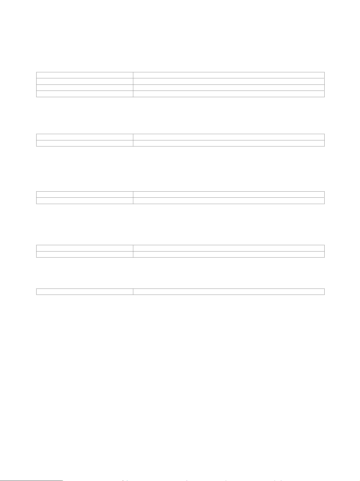
Frequency options
One of the following frequency options must be installed in RF path A:
R&S
®
SMU-B102 100 kHz to 2.2 GHz
R&S
®
SMU-B103 100 kHz to 3 GHz
R&S
®
SMU-B104 100 kHz to 4 GHz
R&S
®
SMU-B106 100 kHz to 6 GHz
One of the following frequency options can be installed in RF path B:
(If R&S
®
SMU-B104 or R&S
®
SMU-B106 and one of the R&S
®
SMU-B20 or R&S
®
SMU-B22 options are installed in RF path A,
no options can be installed in RF path B.)
R&S
®
SMU-B202 100 kHz to 2.2 GHz
R&S
®
SMU-B203 100 kHz to 3 GHz
Enhancement options
Enhanced phase noise performance and FM/φM modulator
One of the following options can be installed in RF path A:
R&S
®
SMU-B20 FM/M modulator
R&S
®
SMU-B22 FM/M modulator and enhanced phase noise performance
These options cannot be installed in RF path B.
High-power output
The following options can be installed
R&S
®
SMU-B31 High-power output (RF path A)
R&S
®
SMU-B36 High-power output (RF path B)
Phase coherence
R&S
®
SMU-B90 Phase coherence
This option can be installed once. It provides phase-coherent RF outputs of two or more RF paths for one or more instruments.

Version 08.00, January 2012
Rohde & Schwarz R&S
®
SMU200A Vector Signal Generator 7
Modulation
Possible modulation types
RF path A
Amplitude modulation, frequency/phase modulation (optional), vector modulation, digital modulation via internal baseband section
(optional), vector modulation via baseband inputs (optional), pulse modulation, wideband amplitude modulation
RF path B
Amplitude modulation, digital modulation via internal baseband section (optional), vector modulation via baseband inputs (optional),
pulse modulation
Simultaneous modulation
In the same RF path
AM FM φM PM WB-AM I/Q DM ARB
Amplitude modulation (AM) / – – – –
Frequency modulation (FM) / –
Phase modulation (φM) – /
Pulse modulation (PM) /
Wideband AM (WB-AM) – / – – –
Vector modulation (I/Q) – – / – –
Digital modulation (DM) – – – / –
ARB – – – – /
= compatible, – = not compatible, switch off each other