HF Circuit .pdf - 第100页
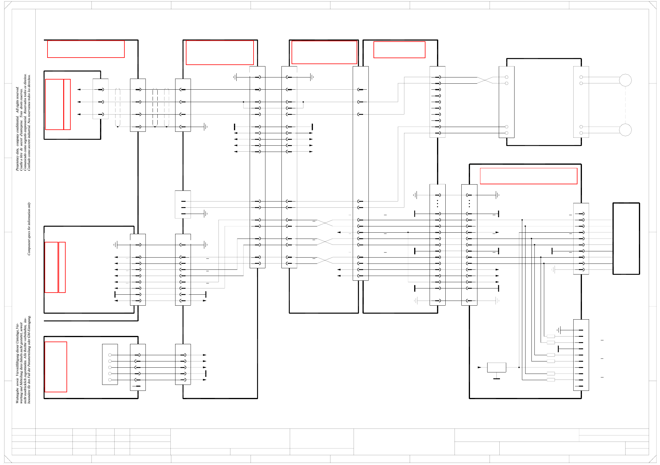
2 - 50 DPCP03 -0101 01LD3 DP axi s, Colle ct&Place head, g antry 3, HF an d HF/3 (Sh. 2 o f 3) 20a,c 18c 26c 24a,c 22c 16c 12c 14c 12A 10c X1uz 8c 10A 8A 6A 6c Servo amplifier SDS 60/1 D1 03002142-xx A16 (un) 12 6 10…
2 - 49
DPCP03-010101LD3 DP axis, Collect&Place head, gantry 3, HF and HF/3 (Sh. 1 of 3)
=
Date
Check.
Stand.
Author
Sheet
Orig. Repl. f. Repl. byNameDateModifiedStatus
Sh.
+
2
F
3
F
8
A
2
D
3
C
A
5
B
41
E
5
41
C
D
DP axis, Collect&Place head
Function st.
s
A&D EA
E
678
76
1.
1.
1.
22.09.05
22.09.05
22.09.05
22.09.2005
Hi
DPCP03-010101LD3
1
3
Hi
Hi
Hi
Product st.
Document st.
SIPLACE HF series
DPCP03-010101LD3_SH01.DWG
CAD file :
Mat. no. :
Gantry 3
00330648-xx (cs)
SP6-12 intermediate distributor board, digital
DLM-X head adapter
03019066-xx (cq)
20
21
23
22
24
25
27
28
26
31
GND
DP track B
31
DP track B
DP track A
DP track A
26
28
27
25
24
22
23
21
20 DP track N
DP track N
X1cs
40
37
34
40
37
34
1919
AGND
PE
+15V
GNDGND
GND
7
10
8
9
1
4
5
6
2
3
X16cs
Track N
Track N
AGND
Track B
Track B
Track A
Track A
Test plug
X22cc/J3
100
102, 104
106
DP motor U
DP motor V
DP motor W
12+5V +5V
X161
2
3, 4
1
PE
DP tachom. -
DP tachom. +
GND
X2cs:22
-15V
VCC
GND
+15V88, 90
-15V87, 89-15V
17
15
DP track A
DP track A
DP track B
DP track B
19
21
DP track N
DP track N23
25
VCC83, 85
VCC
DP tachom. +
DP tachom. -
29
27
23
24
DP tachom. -
DP tachom. +23
24
bu
wh
10
9
8
6
7
5
bk
rd
2
3
4
X12cq
1
Key
Key
DP tachom. +
DP tachom. -
DP motor +
DP motor -
4GND
1
+5V
2
3
7
5
6
8
9
X7cs
10
CP6: 00324968-xx
RSF digital encoder
CP12: 00335990-xx
n.u.
n.u.
6x470 Ω
PE
DP track N
DP track N
DP track B
DP track B
DP track A
DP track A
X14cq
1
PE AGND1
DP track A
DP track A
DP track B
DP track B
DP track N
DP track N
t
M
00321218-xx
5
6
7
8
Motor /tacho
DP axis
3
4
1
2
wh
bu
bk
rd
Interference suppression board
00330573-xx
DP motor
GND
7805
+15V
IN OUT
+5V
GND
+5V
HF and HF/3
Flat ribbon cable
03004333-W1
GND
DP track N
DP track N
DP track B
DP track B
DP track A
DP track A
Track signals, DP axis
X50ca
2
1
3
4
5 +5V
+15V
-15V
+24V
GND
DP1 motor
Cable carrier interface
03009805-xx
DP1 axis
Actual value
03009815-xx
36
37
38
35
X22
wh
gn
bn
bk bk
bn
gn
wh
3
2
X3uz
1
bk
rd
bn
bk
rd
bn
wh
03002164-W2
(Cable)
Gantries 1 or 3 Gantry 3
DP motor U
DP motor V
DP motor W
Servo ampl. backplane
DP axis / Collect&Place head
00353484-xx A42 (uz)
Axis unit
03016110-xx
X3up
1,4,7,17,20,23,26
PE
2
3
5
6
8
9
10
GND
DP track N
DP track N
DP track B
DP track B
DP track A
DP track A
00353487-xx A45 (up)
Axis distributor I/O
Sheet 3/D7
Cable carrier interface
03009808-xx W1/W2
(W1)wh
2
1
KEY
gn
bn
(W2)
(W2)
(W1)
(W1)
wh
or
X1qa_+24V
X1qa_+15V
X1qa_+5V
X1qa_0V
X1qa_-15V
pk
rd
bu
X1qa
1
4
6
5
3
2
X5qa
Voltage
Main distributor
03010004-xx (qa)
SIPLACE HF
Sheet 2 / E7
19+5V +5V19
12
+15V
Head interface
03000901-xx (cc)
5
4
3
2
X8cc
1,10,14,34 PE
28
22
25
16, 31
DP motor U
DP motor V
DP motor W
GND
-15V
+15V
+24V
33
32
30
29
26
27 DP track N
DP track B
DP track A
DP track N
DP track B
DP track A
X8ca
Cable carrier interface
03010612-xx (ca)
Carrier cable 8
03001728-xx
DP1/DP2 motor
5
3
4
2
1,10,14,34
28
25
16, 31
22
+24V
+15V
-15V
GND
PE
27
26
29
30
32
33
X16ca
1
2
3
4 PE
DP motor U
DP motor V
DP motor W
X26ca
1,4,7,17,20,23,26
2
PE
3
5
6
10
8
9
See page 4-18
See page 5-22
See page 5-27
See page 4-7
See page 5-57
See page 5-44
See page 5-61
See page 5-8
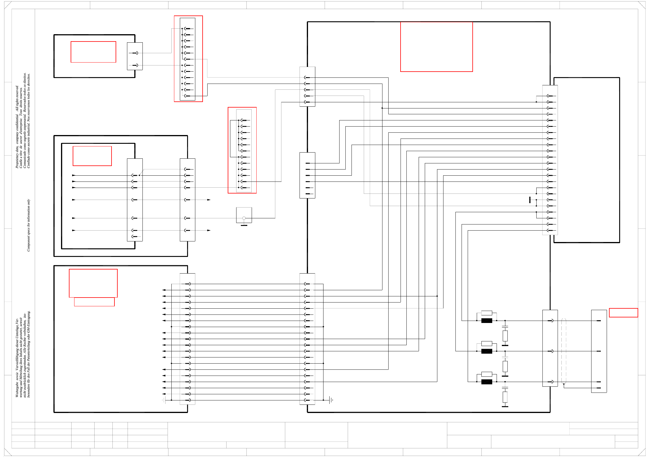
2 - 50
DPCP03-010101LD3 DP axis, Collect&Place head, gantry 3, HF and HF/3 (Sh. 2 of 3)
20a,c
18c
26c
24a,c
22c
16c
12c
14c
12A
10c
X1uz
8c
10A
8A
6A
6c
Servo amplifier
SDS 60/1 D1
03002142-xx A16 (un)
12
6
10
11
9
7
8
3
4
5
1
2
X2uz
6
X5uz
5
4
3
1
2
13
16
17
18
14
15
19
20
n.u.
n.u.
n.u.
n.u.
J²t
PE
Servo Enable +
Servo Enable -
Servo Ready
Inom W
AGND
Inom U
Link voltage impressed
ADR2
ADR1
ADR3
ADR4
X3uz
DP motor W
DP motor V
DP motor U
03002164-W2
(Cable)
20
18
19
17
15
16
X4up
4
5
6
1
2
3
=
Date
Check.
Stand.
Author
Sheet
Orig. Repl. f. Repl. byNameDateModifiedStatus
Sh.
+
2
F
3
F
8
A
2
D
3
C
B
A
5
B
41
E
5
41
C
D
E
DP axis, Collect&Place head
Function st.
s
A&D EA
678
76
1.
1.
1.
22.09.05
22.09.05
22.09.05
22.09.2005
Hi
DPCP03-010101LD3
2
3
Hi
Hi
Hi
Product st.
Document st.
SIPLACE HF series
DPCP03-010101LD3_SH02.DWG
CAD file :
Mat. no. :
18a
28a,c
32a,c
30a,c
X21
13
Power supply
00354626-xx
X13
1
1
03009786-xx W1+W2
(Cable)
4c
4a
2a
2c
-15V
+15V
GND
ADR1
ADR2
ADR3
ADR4
Link voltage impressed
Servo Ready
AGND
Inom W
Inom U
Servo Enable
J²t
R31
L3
L2
R21
L1
R11
DP motor V
DP motor U
DP motor W
Gantry 3
C1
R12
R22
C2
R32
C3
Z/DP+ link voltage
Star+ link voltage
Star+
36
38
37
X22
35
bn
rd
bk
wh
vi
bu
or
wh
142
3
vi11
PE
1
6
4
2
4
3
9
7
12
11
10
9
8
13
14
PE
Flat ribbon cable
20x0.09mm²
X5wo
3d
3e
3c
3b
3A
4a
4d
4b
4c
3f
4e
4f
A42 (uz)
00353484-xx
DP axis / Collect&Place head
Servo backplane
n.u.
n.u.
Link voltage impressed
AGND
Inom W
Inom U
n.u.
Servo Ready
n.u.
Servo Enable -
Servo Enable +
A45 (up)
Axis distributor I/O
00353487-xx
1
2
3
00353449-xx
5V/15V
DC/DC converter
A17
X2wo
d6
d10
or +15V (Servo)
bu -15V (Servo)
Sheet 3 / B7
Sheet 1 / A2
n.u.
n.u.
n.u.
n.u.
n.u.
n.u.
n.u.
n.u.
X4uz
Z/DP+5
4
3
1
2
n.u.
n.u.
n.u.
n.u.
-15V
+15V
GND
bu
or
wh
n.u.
X23
7
bk
wh
bk
16
25
23
n.u.
(W1)
(W1)
(W1)
(W1)
(W1)
(W2)
(W2)
gnye
Z/DP+ link voltage
Star+ link voltage
PE
Z/DP- link voltage
Vin_axis+
Vin_axis-
Z/DP+
4e
4f
3e
4b
4d
4c
4a
3f
X4wo
3b
vi
3d
3c
3A
X3wo:Z28, X2wo:Z28
X3wo:D30, X2wo:Z30
(DC/DC converter)
(DC/DC converter)
12
vi
HF and HF/3
See page 5-19
See page 3-7
See page 5-27
See page 5-22
See page 5-25
See page 5-25
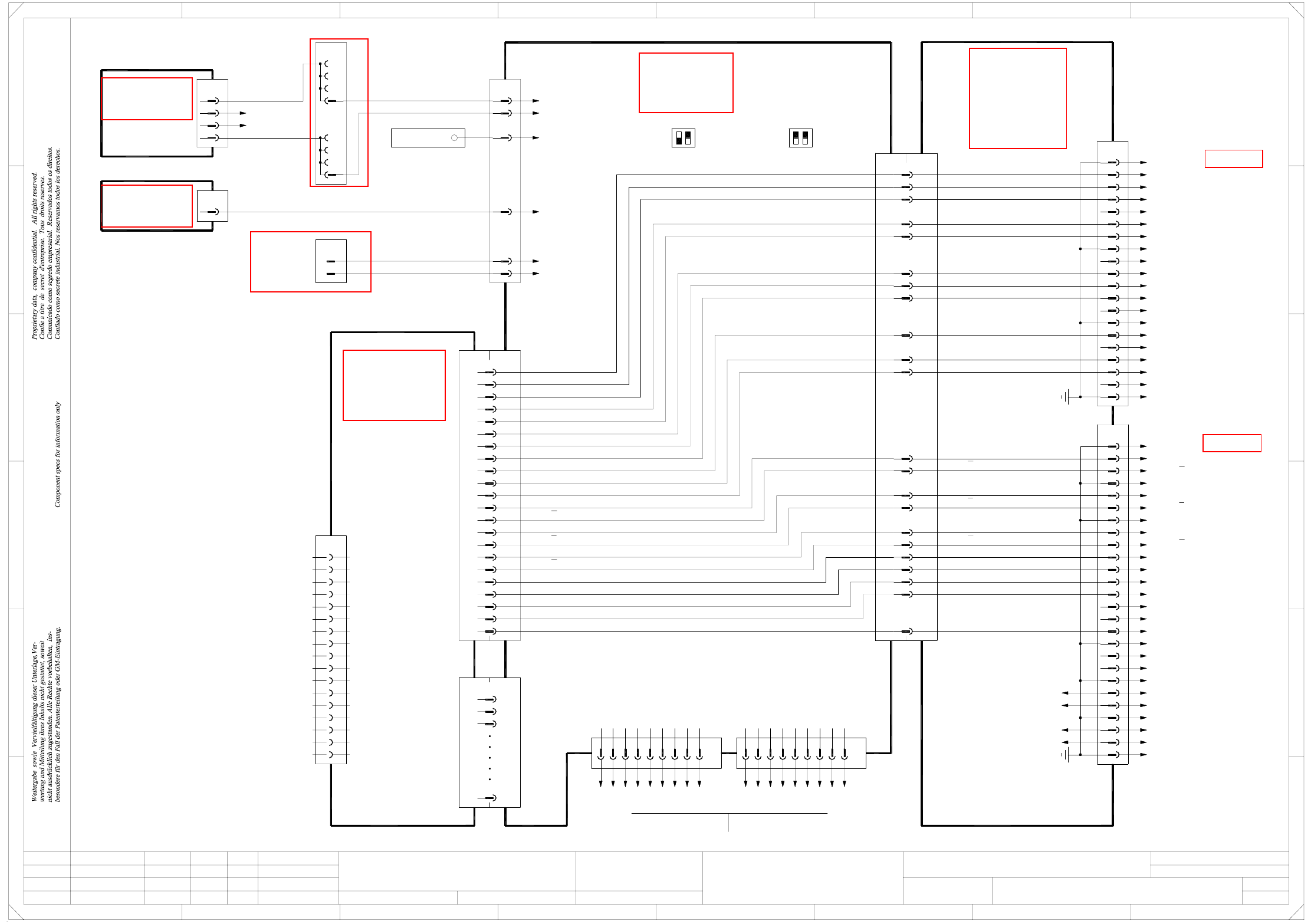
2 - 51
DPCP03-010101LD3 DP axis, Collect&Place head, gantry 3, HF and HF/3 (Sh. 3 of 3)
=
Date
Check.
Stand.
Author
Sheet
Orig. Repl. f. Repl. byNameDateModifiedStatus
Sh.
+
2
F
3
F
8
A
2
D
3
C
B
A
5
B
41
E
5
41
C
D
DP axis, Collect&Place head
Function st.
s
A&D EA
E
678
76
1.
1.
1.
22.09.05
22.09.05
22.09.05
22.09.2005
Hi
DPCP03-010101LD3
3
3
Hi
Hi
Hi
Product st.
Document st.
SIPLACE HF series
DPCP03-010101LD3_SH03.DWG
CAD file :
Mat. no. :
Servo Enable +
Servo Enable -
Servo Ready
Inom W
AGND
Inom U
Link voltage impressed
20
18
19
17
15
16
X4up
4
5
6
1
2
3
7
12
11
10
9
8
13
14
PE
n.u.
n.u.
n.u.
n.u.
n.u.
Flat ribbon cable
20x0.09mm²
n.u.
n.u.
Link voltage impressed
AGND
Inom W
Inom U
n.u.
Servo Ready
n.u.
Servo Enable -
Servo Enable +
A45 (up)
Axis distributor I/O
00353487-xx
PE
1
20
19
17
18
16
14
15
13
7
10
11
12
8
9
4
6
5
3
2
X3up
25
23
24
22
21
26
C21
C19
A13
A12
A19
A20
B14
A14
C18
C16
B16
B20
C20
X7up
B12
A13
A12
DP track A
DP track N
DP track B
DP track N
DP track B
DP track A
A19
C19
A20
B14
C21
A14
C18
C16
B16
B20
C20
Link voltage impressed
Inom W
AGND
Inom U
Servo Ready
Servo Enable -
Servo Enable +
PE
PE
PE
PE
PE
PE
PE
PE
PE
PE
GND
03009815-xx
Act. value, DP1 axis
Gantry 3
GNDA28
GNDA28
Gantry 3
C&P head
C15
+5V
C15
+5V
+5V
HF and HF/3
Axis unitAxis unit
12
5
03010054-xx
n.u.
9
GND
CAN_H
CAN_INT
RESET
7
8
6
X30_1sq
X30_2sq
Flat ribbon cable
03010054-xx
Sheet 1 / D2
Sheet 2 / E3
6
X10sq
3
5
4
2
1
-15V
+15V
GND
VCC
Power failure
Power failure
rd
bk
bk
dkbu
wh
pk
X23
Ground bus bar
DC/DC converter
00353450-xx
±15V
A18
2d
dkbu
dkbu
d22
X3wo
z20
2b
2c
pk
2a
X5wo
1d
1c
1A
1b
dkbu
Z4
d6
pk
pk
+15V axis
-15V axis
-15V / X21:19
+15V / X21:17
5V/15V
00353449-xx A17
DC/DC converter
X2wo
z16 rd VCC
X21
21 bk
12 bk
Power failure
Power failure
S1
ON
OFF
B15
A16
A15
C13
C12
B13
B13
B12
C13
C12
A16
A15
B15
DP track A
DP track A
DP track B
DP track B
DP track N
DP track N
n.u.
PE
n.u.
n.u.
n.u.
n.u.
n.u.
n.u.
n.u.
n.u.
n.u.
n.u.
DP track B
DP track N
DP track N
DP track B
DP track A
DP track A
X6sq
X6sqX2ub
X1ub
A/B/C1
X2sq
A/B/C32
A/B/C2
A/B/C3
SMP bus
A44 (sq)
Backplane, axis
00353485-xx
Axis board, DP axis
A24 (ub)
00350575-xx
13
35
36
37
19
22
23
34
21
20
16
18
17
15
14
X3ub
9
1
VCC
-15V
+15V
TRIG
CAN_L
CAN_H
VREG
GND
INDEX
End signal
COUNT B
COUNT A
Inom
Vnom
RxD
TxD
AGND
CAN bus
RESET
Power failure
1
CAN_L
GND
1-Wire
3
4
2
CAN bus
9
n.u.
Power failure
CAN_INT
GND
CAN_H
8
7
6
5
1-Wire
CAN_L
GND
4
3
2
1
HF: HF/3:
2
S1
1
OFF
ON
See page 5-20
See page 5-19
See page 5-25
See page 4-20
See page 5-27
See page 5-23
See page 5-13