HF Circuit .pdf - 第110页
2 - 60 ZTH032-010201LD3 Z2 axis, T winHead, P&P module 2, gantry 3, HF and HF/3 (Sh. 1 of 4) 8 9 11 10 12 13 14 17 16 20 19 18 21 23 22 24 26 25 15 2 1 3 4 6 7 5 X8cd 30 28 29 27 8 15 25 26 24 22 23 21 18 19 20 16 17…
2 - 59
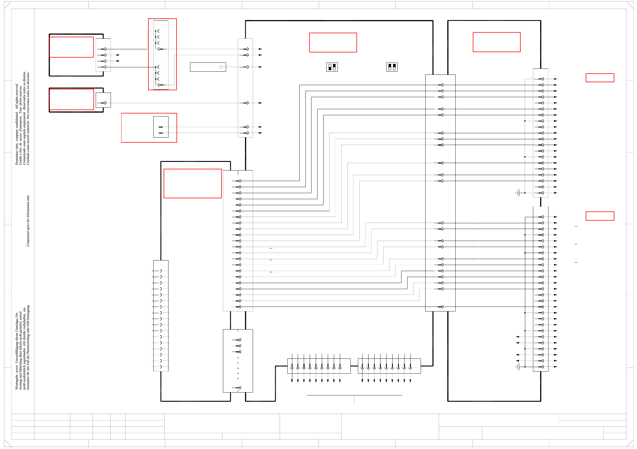
DPTH031-010201LD3 DP1 axis, TwinHead, P&P module 1, gantry 3, HF and HF/3 (Sh. 4 of 4)
Inom U
Link voltage impressed
20
18
19
17
15
16
X4up
4
5
6
1
2
3
7
12
11
10
9
8
13
14
PE
n.u.
n.u.
n.u.
n.u.
n.u.
Flat ribbon cable
20x0.09mm²
n.u.
n.u.
Link voltage impressed
AGND
Inom W
Inom U
n.u.
Servo Ready
n.u.
Servo Enable -
Servo Enable +
A45 (up)
Axis distributor I/O
00353487-xx
PE
1
20
19
17
18
16
14
15
13
7
10
11
12
8
9
4
6
5
3
2
X3up
25
23
24
22
21
26
C21
C19
A13
A12
A19
A20
B14
A14
C18
C16
B16
B20
C20
X7up
=
Date
Check.
Stand.
Author
Sheet
Orig. Repl. f. Repl. byNameDateModifiedStatus
Sh.
+
2
F
3
F
8
A
2
D
3
C
B
A
5
B
41
E
5
41
C
D
E
DP1 axis, TwinHead, P&P module 1
Function st.
s
A&D EA
678
76
1.
2.
1.
09.02.04
22.09.05
22.09.05
09.02.2004
Hi
DPTH031-010201LD3
4
4
Hi
Hi
Hi
Product st.
Document st.
SIPLACE HF series
DPTH031-010201LD3_SH04.DWG
CAD file :
Mat. no. :
Servo Enable +
Servo Enable -
Servo Ready
Inom W
AGND
DP1 track N
DP1 track B
DP1 track A
A19
C19
A20
B14
C21
A14
C18
C16
B16
B20
C20
Link voltage impressed
Inom W
AGND
Inom U
Servo Ready
Servo Enable -
Servo Enable +
PE
PE
PE
PE
PE
PE
PE
PE
PE
PE
GND
03009815-xx
Act. value, DP1 axis
Gantry 3
GNDA28
GNDA28
Gantry 3
TwinHead, P&P module 1
C15
+5V
C15
+5V
+5V
HF and HF/3
Axis unitAxis unit
12
HF: HF/3:
OFF
ON
S1
12
03010054-xx
5
9
n.u.
RESET
CAN_INT
CAN_H
GND
7
8
6
X30_2sq
X30_1sq
Flat ribbon cable
Sheet 1 / D2
Sheet 2 / E3
6
X10sq
3
5
4
2
1
-15V
+15V
GND
VCC
Power failure
Power failure
rd
bk
bk
dkbu
wh
pk
X23
Ground bus bar
DC/DC converter
00353450-xx
±15V
A18
2d
dkbu
dkbu
d22
X3wo
z20
2b
2c
pk
2a
X5wo
1d
1c
1A
1b
dkbu
Z4
d6
pk
pk
+15V axis
-15V axis
-15V / X21:19
+15V / X21:17
5V/15V
00353449-xx A17
DC/DC converter
X2wo
z16 rd VCC
X21
21 bk
12 bk
Power failure
Power failure
S1
ON
OFF
B15
A16
A15
C13
C12
B13
B12
A13
A12
DP1 track A
DP1 track N
DP1 track B
B13
B12
C13
C12
A16
A15
B15
DP1 track A
DP1 track A
DP1 track B
DP1 track B
DP1 track N
DP1 track N
n.u.
PE
n.u.
n.u.
n.u.
n.u.
n.u.
n.u.
n.u.
n.u.
n.u.
n.u.
DP1 track B
DP1 track N
DP1 track N
DP1 track B
DP1 track A
DP1 track A
X8sq
X8sqX2ub
X1ub
A/B/C1
X4sq
A/B/C32
A/B/C2
A/B/C3
SMP bus
A44 (sq)
Backplane, axis
00353485-xx
DP1 axis axis board
A24 (ub)
00350575-xx
13
35
36
37
19
22
23
34
21
20
16
18
17
15
14
X3ub
9
1
VCC
-15V
+15V
TRIG
CAN_L
CAN_H
VREG
GND
INDEX
End signal
COUNT B
COUNT A
Inom
Vnom
RxD
TxD
AGND
03010054-xx
CAN bus
RESET
Power failure
1
1-Wire
GND
CAN_L
3
4
2
CAN bus
9
n.u.
Power failure
CAN_H
GND
CAN_INT
8
7
6
5
GND
CAN_L
1-Wire
4
3
2
1
See page 5-20
See page 5-19
See page 5-27
See page 5-23
See page 5-13
See page 5-25
See page 4-20
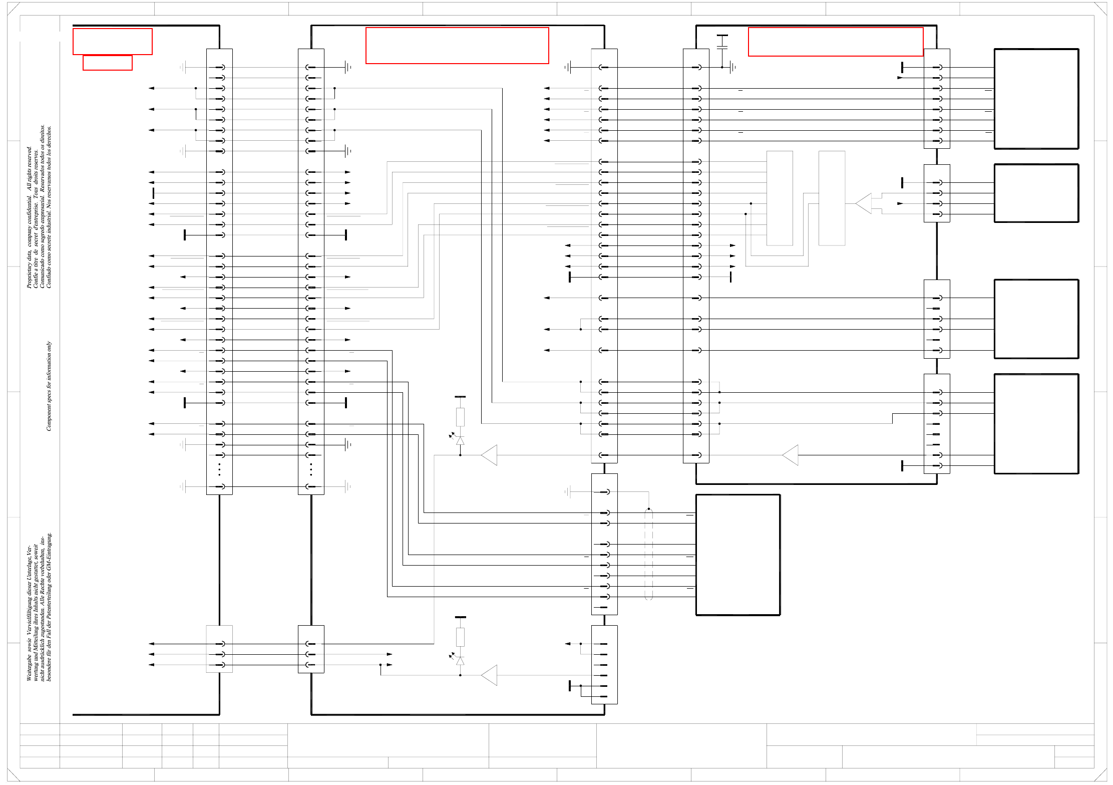
2 - 60
ZTH032-010201LD3 Z2 axis, TwinHead, P&P module 2, gantry 3, HF and HF/3 (Sh. 1 of 4)
8
9
11
10
12
13
14
17
16
20
19
18
21
23
22
24
26
25
15
2
1
3
4
6
7
5
X8cd
30
28
29
27
8
15
25
26
24
22
23
21
18
19
20
16
17
14
13
12
10
11
9
5
7
6
4
3
X8ce
1
2
03005289-xx
DP unit control cable
PE PE
DP2 track N
DP2 track N
DP2 track B
DP2 track B
DP2 track A
DP2 track A
GND
X30cd:32
C600 head main board, P&P module 2
00352833-xx (cd) 00352809-xx (ce)
C700 TwinHead force meas. board, P&P module 2
Force sensor
X30cd:33
X30cd:30
X30cd:29
X30cd:26
X30cd:27
DP1 track N
DP1 track B
DP1 track B
DP1 track A
DP1 track N
DP1 track A
GND
Z1-Force-DATA
Z1-Force-DATA
Z1-Force-CS
Z1-Force-CS
Z1-Force-Dir
Z1-Force-Dir
Z1-Force-SCLK
Z1-Force-SCLK
-15V
+15V
+5V
-15V
+15V
+5V
DP2 motor U
DP2 motor V2
DP2 motor V1
DP2 motor W
Z2 motor V
Z2 motor U
Z2 motor W
Z2 temperature sensor
X30cd:6, 7
=
Date
Check.
Stand.
Author
Sheet
Orig. Repl. f. Repl. byNameDateModifiedStatus
Sh.
+
2
F
3
F
8
A
2
D
3
C
B
A
5
B
41
E
5
41
C
D
Z2 axis, TwinHead, P&P module 2
Function st.
E
678
76
1.
2.
1.
09.02.04
22.09.05
22.09.05
09.02.2004
Hi
ZTH032-010201LD3
1
4
Hi
Hi
Hi
Product st.
Document st.
SIPLACE HF series
ZTH032-010201LD3_SH01.DWG
CAD file :
Mat. no. :
27
29
28
30
X30cd:4, 5
X30cd:2, 3
Z1 motor V
Z1 motor U
Z1 motor W
Z2 temperature sensor
DP1 motor W
DP1 motor V
DP1 motor U
or D15
C37
220n
DP2 axis
7
8
1
3
2
4
6
5
T1
RSF encoder
+5V
GND
X18ce
03000046-xx
+5V
GND
T2
T2
T1
RI
RI
2
1
3
4
X16ce
6
5
DP2 axis
03001556-xx
DISC-Magnetic-Motor
A+ (U)
A- (V)
B+ (V)
B- (W)
Key
Key
gy
bu
bn
ye
8
5
7
6
4
3
X17ce
GND
1
2
Key
Key
Key
ye
bn
00353135-xx
Linear motor
Z2 motor
gy
wh
bu
Temperature sensor
4
3
X15ce
1
2
Force transducer
03000100-xx
OUT -
U-Sensor +
GND
OUT +
J13 J12
7
2
1
6
14
10
9
15
Z2 track A
Z2 track A
PE
d6green
X30cd
24
21 Z2 reference point
Z2 temperature sensor
X2cd:78
Z2 reference point
Sheet 2
03004332-W3
Twin flat ribbon cable loom
23
Z2 clamping
X32cr
24
23
21
Z2 temperature sensor
Z2 clamping
Z2 reference point
Gantry 3
HF and HF/3
A&D EA
s
32
35
34
33
50
+5V7
RI
2
3
4
X5cd
GND
1
8
GND
T1
T2
T2
T1
1
4
6
5
3
2
X4cd
Z2 axis
03000102-xx
Encoder
10
9
RI
6
5
bk
gy
bn
gn
wh
rd
pk
ye
whgn
Key
Key
+5V
PE
03000902-xx (cr)
P&P head adapter
Key
Z2 motor U
Z2 motor V
Z2 motor W
PE
Gantry-ID-Bit 0
Gantry-ID-Bit 1
Gantry-ID-Bit 2
Power-Fail
Z2-Force-Dir
Z2-Force-Dir
GND
GND
VCC
-15V
+15V
Z2-Force-CS
Z2-Force-CS
Z2-Force-SCLK
Z2-Force-SCLK
Z2-Force-DATA
Z2-Force-DATA
PE
n.u.n.u.
PE
PE
GNDGND
+24V+24V
Z2 track N
Z2 track N
Z2 track B
Z2 track B
Z2 track A
Z2 track A
Z2 track N
Z2 track N
Z2 track B
Z2 track B
Z2 track A
Z2 track A
Z2 track N
Z2 track N
Z2 track B
Z2 track B
3
2
GND
U-Sensor+
-
1
28
30
29
25
26
27
24
6
22
23
21
19
20
16
18
17
11
14
15
13
12
8
10
9
7
1
3
5
4
2
X31cd
50
35
33
34
32
31
PE
PE
Key
PE
GND
Z2-Force-Dir
Z2-Force-Dir
Z2-Force-CS
Z2-Force-CS
Z2-Force-DATA
Z2-Force-DATA
Z2-Force-SCLK
Z2-Force-SCLK
+5V
-15V
+15V
Gantry-ID-Bit 0
Gantry-ID-Bit 1
Power-Fail
P&P-Head-ID-Bit
Z2 motor W
Z2 motor V
Z2 motor U
Twin flat ribbon cable loom
03004332-W4
X33cr
28
29
25
27
26
24
6
22
23
21
20
19
17
18
16
11
14
15
12
13
8
9
10
7
1
3
5
4
2
30
31
See page 5-16
See page 5-15
See page 5-46
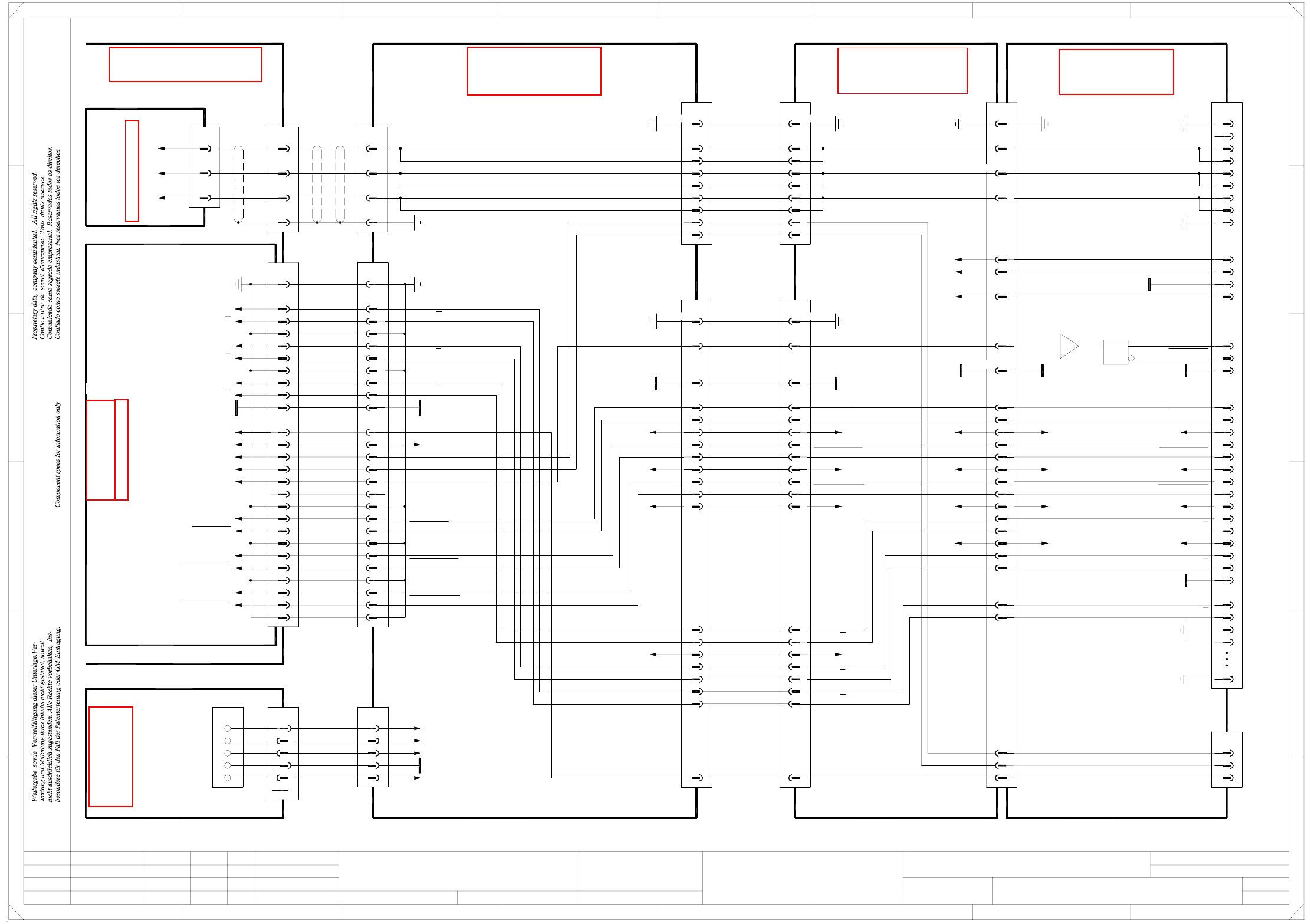
2 - 61
ZTH032-010201LD3 Z2 axis, TwinHead, P&P module 2, gantry 3, HF and HF/3 (Sh. 2 of 4)
22
23
21
20
19
17
18
16
11
14
15
12
13
8
9
10
7
1
3
5
4
2
30
31
32
35
34
33
50
PE
03000902-xx (cr)
P&P head adapter
Key
Z2 motor U
Z2 motor V
Z2 motor W
PE
Gantry-ID-Bit 0
Gantry-ID-Bit 1
Gantry-ID-Bit 2
Power failure
Z2-Force-Dir
Z2-Force-Dir
GND
GND
VCC
-15V
+15V
Z2-Force-CS
Z2-Force-CS
Z2-Force-SCLK
Z2-Force-SCLK
Z2-Force-DATA
Z2-Force-DATA
n.u.
PE
PE
GND
+24V
Z2 track N
Z2 track N
Z2 track B
Z2 track B
Z2 track A
Z2 track A
From sheet 1
X32cr
24
23
21
Z2 temperature sensor
Z2 clamping
Z2 reference point
83,85
28
22
24
7,13,134,140
135
1
133
=
Date
Check.
Stand.
Author
Sheet
Orig. Repl. f. Repl. byNameDateModifiedStatus
Sh.
+
2
F
3
F
8
A
2
D
3
C
B
A
5
B
41
E
5
41
C
D
Z2 axis, TwinHead, P&P module 2
Function st.
E
678
76
1.
2.
1.
09.02.04
22.09.05
22.09.05
09.02.2004
Hi
ZTH032-010201LD3
2
4
Hi
Hi
Hi
Product st.
Document st.
SIPLACE HF series
ZTH032-010201LD3_SH02.DWG
CAD file :
Mat. no. :
X33cr
28
29
25
27
26
24
6
107,109
108,110,112,114
X22cc/J3
111,113
91,92
PE
X14cc:73
X14cc:71
X13cc:73
2
3
1
U2
I1
U1
Z2-Dir
16
12
88,90
14
20
87,89
18
GND
PE
GND
VCC
-15V
+15V +15V
-15V
VCC
66
2
4
8
6
84,86
10
51
26
+24V
+24V
Gantry 3
C600 head interface
03000901-xx (cc)
X6cc
14
12
8
4,5
1,8,9,10,34
2
PE
X6ca
7
12
14
4
6
5
1,8,9,10,34
3
2
PE
03010612-xx (ca)
Cable carrier interface
Gantries 1 or 3
6,7
9
3
Z2 motor W
Z2 motor V
Z2 motor U
S/Z2 motor
Carrier cable 6
03001726-xx
16,31
15
16,31
15
18
20
19
17
18
20
19
17
22
25
24
rd
bk
(Cable)
bnbn34
Z2 motor W3
45 bk bk 4 PE
rd 40 gn
X22
46 wh
gn
wh
03009802-xx
Cable carrier interface
Z2 motor V
Z2 motor U
2
1
X13ca
S/Z2 motor
Voltage
+5V +5V
Z2-Force-DATA
Z2-Force-DATA
Z2-Force-SCLK
Z2-Force-SCLK
Z2-Force-CS
Z2-Force-CS
Z2-Force-CS
Z2-Force-CS
Z2-Force-SCLK
Z2-Force-SCLK
Z2-Force-DATA
Z2-Force-DATA
Z2 temperature sensor
Z2 temperature sensor
Z2 reference point
Z2 reference point
Z2-Dir
Z2-Dir
Z2 clamping
Z2 clamping
Gantry 3
wh
HF and HF/3
X5ca X5cc
1,11,14,34
PE1,11,14,34PE
03001725-xx
Carrier cable 5
X motor
3
6
5
4
2
A&D EA
s
23
21
22
25
24
23
21
GND GND
Z1-Dir
+5V+5V
-15V-15V
+15V+15V
Z2-Force-CS
Z2-Force-CS
Z2-Force-SCLK
Z2-Force-SCLK
Z2-Force-DATA
Z2-Force-DATA
Z2 clamping
Z2 reference point
30
32
33
27
29
28
26
30
32
33
27
29
28
26
+24V +24V
15
15 Z2 temperature sensor
Z2 track A
Z2 track A
Z2 track B
Z2 track B
Z2 track N
Z2 track N
or
03010004-xx (qa)
X1qa_+24V
X1qa_+15V
Main distributor
SIPLACE HF
X1qa_+5V
X1qa_0V
X1qa_-15V
wh
pk
bu
rd
X1qa
(W1)wh1
+24V
1
Cable carrier interface
03009808-xx W1/W2
(W1)
(W1)
(W2)
(W2)
14
6
5
KEY
2
3
2
gn
bn
4
5
3
2
+5V
GND
+15V
-15V
X5qa X50ca
23 23
24
25
26
26
24
25
1
3
4
2
6
5
8
9
11
12
10
7
15
14
16
13
18
17
19
21
20
22
Axis distributor I/O
00353487-xx A46 (uo)
Sheet 4/D7
n.u.
Z2 track B
GND
Z2 track B
Z2 track N
Z2 track N
Z2 track A
Z2 track A
PE
11
17
20
21
22
18
19
14
15
16
n.u.
12
13
X5uo
S/Z2 axis
Actual value
8
10
9
7
6
GND
4
5
3
X23ca
PE1
2
03009813-xx
Z2 track A
Z2 track A
Z2 track B
Z2 track B
Z2 track N
Z2 track N
03002164-W4
bn
bk
Sheet 3 / E7
00353484-xx A37 (uv)
Z2 axis / TwinHead
Servo ampl. backplane
Z2 motor W bn3
03016110-xx
Axis unit
Z2 motor V
Z2 motor U
X3uv
2
1
See page 4-18
See page 5-57
See page 5-44
See page 5-46
See page 5-27
See page 4-7