HF Circuit .pdf - 第152页
2 - 102 LPET-010301LD3 PCB sing le conve yor / PCB dual co nveyor, track 1 conversi on board "conveyor" (Sh. 5 of 8) LPET-01030 1LD3_SH05.DWG Stromlaufplan/Circuit diagram SIPLACE H F Serie s X12kt X13kt X15kt …
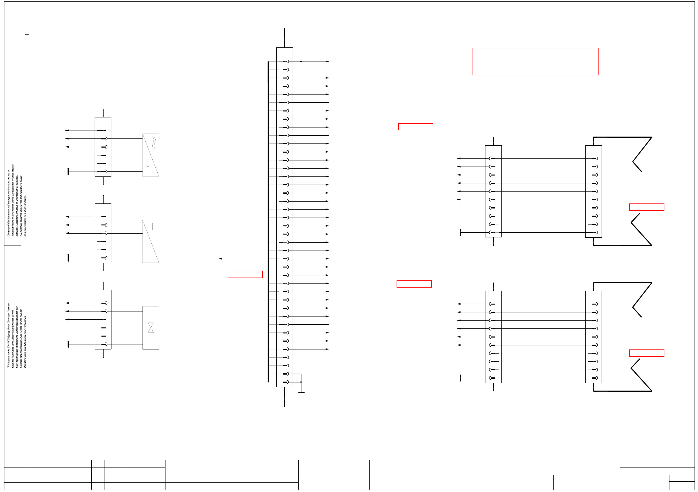
2 - 101
LPET-010301LD3 PCB single conveyor / PCB dual conveyor, track 1
conversion board "conveyor" (Sh. 4 of 8)
Status
01.
01.
Doc. status
Modified
Function status
Product status
Date
Hi
Hi
Hi
Name Stand.
Check.
Date
Author Hi
CAD file:
Mat. no.:
Orig./Repl.f/Replaced by
LPET-010301LD3
Sh.
Sh.8
4
(kt) 00359425-xx
Conversion board, "conveyor"
27
34
33
32
29
31
30
28
8
22
26
25
24
23
20
21
19
18
13
15
17
16
14
12
11
10
9
6
7
5
4
1
3
2
X53kt
+24V-
35
36
37
38
39
40
A2.3
A2.4
A2.5
A2.6
A2.7
A2.8
A2.9
A2.10
A2.11
A2.12
A2.13
A2.14
A2.15
A2.16
A2.17
A2.18
A2.19
A2.20
A2.21
A2.22
A2.23
A2.24
A2.25
A2.26
A2.27
A2.28
A2.29
A2.30
A2.31
A2.32
A2.33
A2.34
GND
Conveyor control
(sheet 1)
TSP-301 (ao)
To plug X13ao
00365548-W3
(cable)
A2.35
A2.36
2
4
5
3
6
7
8
1
4
6
8
7
5
00369020-xx
3
2
X1kt
1
(cable)
X6lv
9
10
GND
9
10
(lv)
Lifting table
Placement sector 1
(sheet 8)
00362766-xx
Conversion board
A1.4
A1.37
A1.38
A1.13
A1.3
+24V-
Lifting table 1, valve down
Lifting table 1, valve up
Lifting table 1, track B
Lifting table 1, limit switch
Lifting table 1, track A
10
GND
9
8
10
9
8
Lifting table 2, valve up
Lifting table 2, valve down
Lifting table 2, track B
A1.6 3
Lifting table 2, limit switch
A1.40
7
6
A1.39
A1.14
4
5
Lifting table 2, track A
+24V- 1
A1.5
2
X2kt
00369071-xx
(cable)
3
Placement sector 2
7
6
4
5
00362766-xx
(sheet 8)
(lw)
Lifting table
Conversion board
1
2
X6lw
All connections from A1.xx
to plug X52kt
to plug X52kt
All connections from A1.xx
PCB single conveyor / PCB dual conveyor, track 1
Conversion board, "conveyor"
X29kt
X10kt
+24V-
GND 6
5
4
3
A1.46
1
2
GND 6
5
4
A1.18
+24V-
1
3
2
GND 6
5
A1.34
+24V-
4
3
1
2
X7kt
Width adjustment
Adjustment drive 3, valve
wh
Key
Width adjustment
00365571-xx
bk
Adjustment drive 3, cylinder switch
bl
Key
00365572-xx
bn
bk
00365573-xx
bl
Key
bn
bk
Adjustment drive 3, sensor
Width adjustment
A1.11
A2.27
A2.28
s
A&D EA
03.
20.03.03
22.09.05
22.09.05
20.03.2003
(sheet 3)
(sheet 3)
LPET-010301LD3_SH04.DWG
Stromlaufplan/Circuit diagram
SIPLACE HF Series
See page 5-32
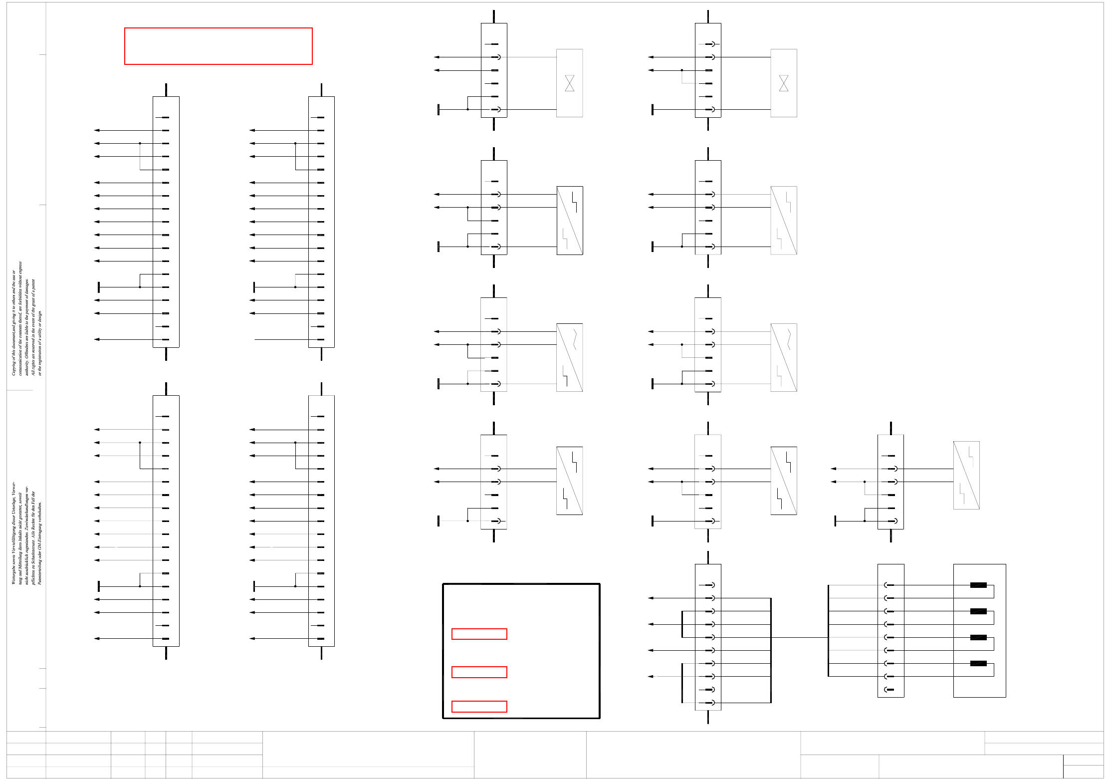
2 - 102
LPET-010301LD3 PCB single conveyor / PCB dual conveyor, track 1
conversion board "conveyor" (Sh. 5 of 8)
LPET-010301LD3_SH05.DWG
Stromlaufplan/Circuit diagram
SIPLACE HF Series
X12kt
X13kt
X15kt
X14kt
X16kt
PCB sensor, placement sector 1 (option)
PCB sensor, output conveyor (option)
PCB sensor, placement sector 2 (option)
PCB sensor, intermediate conveyor (option)
PCB sensor, input conveyor (option)
to plug X51kt
All connections from SM_xx
PLEASE NOTE:
All connections from A1.xx
to plug X52kt
All connections from A2.xx
to plug X53kt
PCB single conveyor / PCB dual conveyor, track 1
Conversion board, "conveyor"
s
A&D EA
03.
20.03.03
22.09.05
22.09.05
20.03.2003
Key
rd
bn
Key
ye
pk
gn
ye
pk
gr
bl
rd
rd
(sheet 3)
(sheet 3)
(sheet 4)
A2.36
A2.35
A2.34
Key
18
17
16
15
A2.20
A2.19
A2.18
A2.15
A2.17
A2.16
A2.26
12
13
11
10
7
9
8
6
SOKO/options
Placement sector 2
A2.25
+24V-
A2.24
X35kt
Key
4
3
2
1
5
14GND
A2.36
A2.35
A2.34
18
17
Key
16
15
A2.20
A2.19
A2.18
12
13
11
10
A2.15
A2.17
A2.16
A2.26
7
9
8
6
X37kt
A2.25
+24V-
A2.24
4
3
2
1
Key
X30kt ... X33kt not used
X6kt, X8kt, X9kt, X11kt, X18kt not used
wh
bk
5
6
4
3
X41kt
2
1
+24V-
Key
GND
A1.43
Width adjustment
Adjustment drive 1, valve Adjustment drive 2, valve
Width adjustment
GND 6
5
wh
A1.44
+24V-
bk
2
Key
3
4
X45kt
1
X46kt
GND 6
5
bl
GND 6
5
Width adjustment
Adjustment drive 1, cylinder switch
X42kt
2A1.19
+24V- 3
4
1
bk
Key
Width adjustment
Adjustment drive 2, cylinder switch
2A1.20
+24V- 3
4
1
Key
bl
bk
bn
00369016-xx
00369014-xx
00369015-xx
00369017-xx
bn
X47kt
Width adjustment
Adjustment drive 1, sensor
55
GND
6
00369018-xx
bl
GND 6
X43kt
+24V-
4
3
A1.21
1
2
bn
Key
bk
+24V-
4
3
A1.22
1
2
Adjustment drive 2, sensor
Width adjustment
00369019-xx
bl
Key
bn
bk
X48kt
GND 6
5
00365775-xx
Key
GND 6
5
Limit switch, right spindle
Width adjustment
X44kt
2A1.23
+24V-
3
4
1
bn
wh
Limit switch, left spindle
2A1.24
+24V- 3
4
1
Width adjustment
00365776-xx
bn
wh
Key
1
4 4
1
00372913-xx
4
SM_B+
5
6
SM_A-
SM_A+
3
2
wh
X40kt
1
bk
or
X49kt
7
8
9
10
SM_B-
gn
gr
bl
(cable)
4
1
3
2
5
6
7
8
9
bn
wh
ye
bl
bn
wh
gn +
-
-
+
+
-
-
+
A
A
B
B
"Width adjustment"
00360901-xx
Step motor
5
GND 6
X19kt
+24V-
A1.17
4
3
Key
wh
2
1
bn
4
1
"Width adjustment, right-h. side"
00365777-xx
Limit switch
Status
01.
01.
Doc. status
Modified
Function status
Product status
Date
Hi
Hi
Hi
Name Stand.
Check.
Date
Author Hi
CAD file:
Mat. no.:
Orig./Repl.f/Replaced by
LPET-010301LD3
Sh.
Sh.8
5
(kt) 00359425-xx
Conversion board, "conveyor"
4
6
8
7
5
3
2
X34kt
1
9
10
A2.23
A2.22
A2.21
Key
+24V-
11
12
13
14
15
16
17
18
GND
A2.9
A2.10
A2.11
A2.12
A2.13
A2.14
A2.31
A2.32
A2.33
Key
Placement sector 1
SOKO/options
A2.14 12
A2.33
18
17
Key
A2.32
A2.31
GND
16
15
14
13
A2.13
A2.12
A2.11
A2.10
11
10
8
9
A2.9
A2.23
+24V-
A2.22
5
6
7
4
3
Placement sector 1
A2.21
SOKO/options
X36kt
2
1
Key
Placement sector 2
SOKO/options
5
14GND
See page 5-32

2 - 103
LPET-010301LD3 PCB single conveyor / PCB dual conveyor, track 1
conversion board „Transportation cheek A“ (Sh. 6 of 8)
00370206-xx
bk
Receiver, output conveyor
X10kv
1
2
Key
bl
5
6
4
3
Light barrier
00370205-xx
bk
Receiver, placement sector 2
X9kv
1
2
Key
bl
6
5
4
3
EA0 2
bk
2
bk
Light barrier
00370204-xx
Receiver, intermediate conveyor
X8kv
1
bl
6
5
3
4
Light barrier
00370203-xx
Key
Receiver, placement sector 1
X7kv
1
Key
bl
6
5
3
4
Light barrier
00370202-xx
Receiver, input conveyor
X6kv
1
bn
+24V-
bn
bn
bn
bn
GND
GND
EA1
+24V-
GND
EA2
+24V-
GND
EA3
+24V-
GND
EA4
+24V-
EA7
GND
+24V-
EA9
GND
+24V-
EA8
GND
+24V-
EA5
EA6
GND
+24V-
GND
+24V-
bn
2
5
6
4
3
Not used
1
2
X15kv
5
6
LPET-010301LD3_SH06.DWG
Stromlaufplan/Circuit diagram
SIPLACE HF Series
22
31
34
33
32
29
30
28
27
24
26
25
23
3
17
21
20
19
18
15
16
14
13
8
10
12
11
9
7
6
5
4
X16kv
1
2
Placement sector 1
4
Key
MOT2-
wh
6
5
MOT2+
Cable, belt motor
bn
3
2
X2kv
1
00365720-xx
M
Intermediate conveyor
4
Key
MOT3-
wh
6
5
MOT3+
Cable, belt motor
bn
3
2
X3kv
1
00365761-xx
M
Placement sector 2
4
Key
MOT4-
wh
6
5
MOT4+
Cable, belt motor
bn
3
2
X4kv
1
00365762-xx
M
Output conveyor
4
Key
MOT5-
wh
6
5
MOT5+
Cable, belt motor
bn
3
2
X5kv
1
00365763-xx
M
2
bk
bl
5
6
4
3
Light barrier
Key
4
3
Not used
1
2
X14kv
Key
wh
6
5
4
3
gn
2
gn
2
Limit switch, width adjustment
00365765-xx
1
X13kv
wh
Key
bn
6
5
3
4
Receiver module, placement sector 2
00365774-xx
Light barrier
1
X12kv
wh
bn
6
5
3
4
Receiver module, placement sector 1
00365772-xx
Light barrier
Key
1
X11kv
4
1
Conversion board, "transportation cheek A"
2
1
3
X10.1
W2 W1
2
1
X5.1
W2 W1
W2 W1
X9.1
2
1
3
3
X6.1
2
1
W1W2
2
X1.1
1
W2 W1
PCB single conveyor / PCB dual conveyor, track 1
s
A&D EA
03.
20.03.03
22.09.05
22.09.05
20.03.2003
bn
wh
bk
bn
bl
bk
bn
bl
bn
whwh
bn
bk
bn
bl
bk
bl
bn
2
Status
01.
01.
Doc. status
Modified
Function status
Product status
Date
Hi
Hi
Hi
Name Stand.
Check.
Date
Author Hi
CAD file:
Mat. no.:
Orig./Repl.f/Replaced by
LPET-010301LD3
Sh.
Sh.8
6
Conversion board, "transportation cheek"
wh
bn
5
6
4
3
X1kv
2
1
Key
MOT1-
MOT1+
MOT5-
MOT5+
MOT4-
MOT4+
MOT3-
MOT3+
MOT2-
MOT2+
MOT1-
MOT1+
(sheet 3)
"Conveyor"
Conversion board
To plug X54kt
00365723-xx
(cable)
(kv) 00359424-xx
Side panel A
GND
EA0
EA2
EA4
EA6
EA8
EA1
EA3
EA5
EA7
EA9
+24V-
00359425-xx
M
Cable, belt motor
Input conveyor
00365719-xx
See page 5-31