HF Circuit .pdf - 第190页
4 - 3 0036554 3-020 201ZD3 Control com plete, P CB sin gle con veyor (Sh . 1 of 2 ) B D Stand. Check. Author Dat e Status Modified Date Orig . Re pl. f. R epl. by 2 1 Nam e Ground connection accord ing to drawing 0034360…
4 - 2
00354626-110401TD1 Power supply unit (Sh. 2 of 2)
1
1
91010
4
7
1
67
1
1
655
137
115
110
105
102
95
102
175
-
+
2
1
+
-
3
2
1
3
1
2
+
-
F21, F22, F23
Z2
--0.5-0.8NmX102
0.5Nm --
M8 12Nm
M6 8Nm
M5 3.8Nm
M4 1.9Nm
M3 0.8Nm
Torque
0.4Nm
Thread size
M2.5
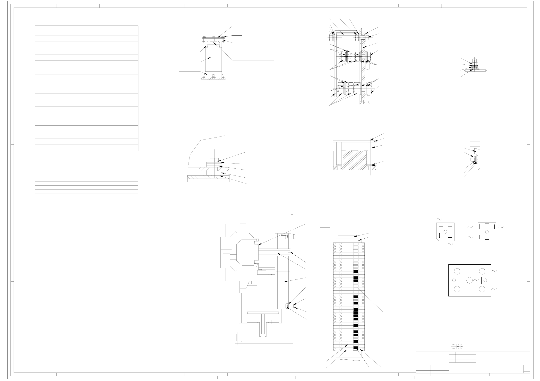
Torques for nuts, screwed onto mold-in threaded bolts,
unless otherwise noted. (TNK does not apply.)
103
118
100
140
K
30
9, 90, 110, 115
Terminal block X20
52 One each between the potentials
141 Printed as shown
51
53
1
1
171819
1
1
1
1
15
1
1
1312 14
4
16
1
1110
RGP
X20
A
B
C
D
E
F
G
H
12
3
456789
12
3
4
5678910
11 12
A
B
C
D
E
F
G
CONFIADO COMO SECRETO INDUSTRIAL
RESERVADOS TODOS LOS DERECHOS
PROPRIETARY DATA
ALL RIGHTS RESERVED
ALLE RECHTE VORBEHALTEN
ALS BETRIEBSGEHEIMNIS ANVERTRAUT
1
323
1
44 4
7
4
4
1
330
4
4
8
1
11
1
4040
4
4
7
30
4
1
211
1
4
2
23
3
23
2
2
23
3
3
2
5
23
6
3
2
8
9
3
2
23
3
56
5
2
6
3
2
2
56
3
3
23
5
23
6
5
2
3
6
89
2
89
3
5
5
23
6
6
56
2
56
3
3
2
Wago line jumper, pos. 174:
Make sure to cut off one connector from the line very short.
(connector no longer used).
Strip back the insulation from the line end 10mm and crimp wire end ferrule onto pos. 176.
- Plug connector in X20-9 socket, wire end ferrule in T1-R13; tighten with 0.8 Nm.
80
59 (2x)
60
89
D
Tighten nut until the upper plastic disks have a convex shape.
59 (T1: 2x, T2: 3x)
102
105
110
G
115
Cable lug
120
105
94
121
106
122
107
B
102115
106
133
105
105
123
116
111
107
117
112
43, 79 (centrally)
C
(3x)
E
54
58, 85
109
104
104, 109, 126
34, 108, 103, 113
33
34, 108, 103, 113
37
A
35
103, 140
36, 88 press-fit and solder up.
Insulate with heat-shrinkable tubing
Aux. line
Torque
Designation
Main line
Torque
-
-
-
-
-
-
-
-
-
-
-
1.0Nm
-
-
-
0.8-1.2Nm
0.8-1.2Nm
0.8-1.2Nm
0.8-1.2Nm
-
-
-
-
-
-
0.8-1.2Nm
0.8-1.2Nm
3Nm
1.7Nm
3-4.5Nm
2-2.5Nm
-
0.8-1.2Nm
1.5-1.8Nm
2.5-3NmFx
-
-
3Nm
2NmC1, C2
U3, U6, U60
Z1
Kx
Terminals 1.5Nm
Ground bolts 3Nm
0.5-0.8Nm
U1, U2, U7, U9, U70
U4, U5, U8, U10, U11
F131, F132, F141, F142
F61, F62, F81, F82
4Nm
hand-screwed
Attachment on the casing
Torque
3-4Nm
2.5Nm
Technical aspects
ISO 2768 - mH
Untol. dimens. to
Scale: Weight:
SIPLACE HF series
Power supply unit
Type 4AV1302-1CT00-1M
BRW1TZAV109-01
Replaced by
AutoCAD
2/2
Sheet
SIEMENS
A&D
Repl. f.
DM
Westermann
Linneck
Cramer
19.03.2002
Date
Author
Check.
Stand.
Document no.:
00354626-110401TD1
DateModifiedStat. Name
12.07.05
25.01.05
26.05.05
T8949
T9804
1N
1Q
T96821P
Cramer
Cramer
Cramer
Sc 1:1
(RGP 1-20, Numbering sequence from bottom to top)
Sc 1:1
(Rectifier section)
Sc 1:1
Sc 1:1
2x annular cable lug
2x annular cable lug
X12 M8
X11 M10
Rectifier connections defined in the drawing
Sc 1:1
Sc 1:1
Sc 1:1
Sc 1:1
Transformer attachment
M/
K2, K3, K4
1.)
2.)
4.)
3.)
K6
K1
K5
Q2
Q1
Run line through handle, fit cable gland and bracket; do not fit the bracket on the base.
Fixing bolt for bracket (pos. 8) with pos. 100 and 113 (do not tighten).
Prevent touching the negative poles of U3, U6, and U60 by covering them with pos. 86 and pos. 87.
Fit pos. 55, 56, and 57 with heat-conductive paste.
Do not fit the rotary drive, put in a polyethylene bag (Pos.76) and keep with device .
Fit insulating tube over the fixing bolts at X1-11 connector.
Min. distance between lines and transformers 10mm.
Combine transformer lines with pos. 70 up to cable duct.
Combine transformer lines with pos. 71 up to cable duct.
6.)
8.)
7.)
5.)
The blades for the retainers (pos. 29 and 30) must point to the center of the top hat rail.
Fit all contact washers with the teeth pointing to the EPS surface.
Cut pos. 40, 41, and 42 to length as per drawing BRW1TZAV109-01.
Fit pos. 73 as shown. In contrast to the illustration, fit the Fx fuse designations top side.
Unspecified torques as per TNK 116-03 and -09.
Hand-screw plastic connections and observe the low sturdiness.
Wiring as per TG6999140-02 (pos. 72, not illustrated). The other cable harness assemblies and lines as per TBV.
Switch as per TNK 116-09. The cables must not protrude over the basic module external dimensions.
Cut pos. 83 and 84 to length as per drawing BRW1TZAV109-01.
Fit transformers centrally.
Packaging pos. 77 not shown. Packaging as per TT62034-02.
Fit unfolded machine label (pos. 160) to jack ring of T1 with pos 161 over T1.
Cable duct fittings: use disk pos. 119 between base and cable duct for embossed locations.
Make sure not to distort the transportation lock against the DC/DC converter.
Fit transportation lock pos. 157 above the DC/DC converters in the base plate slot toghether with pos. 158 and 103.
Attention : Do not pinch the insulating collars of the wire end ferrules during wiring!
4 - 3
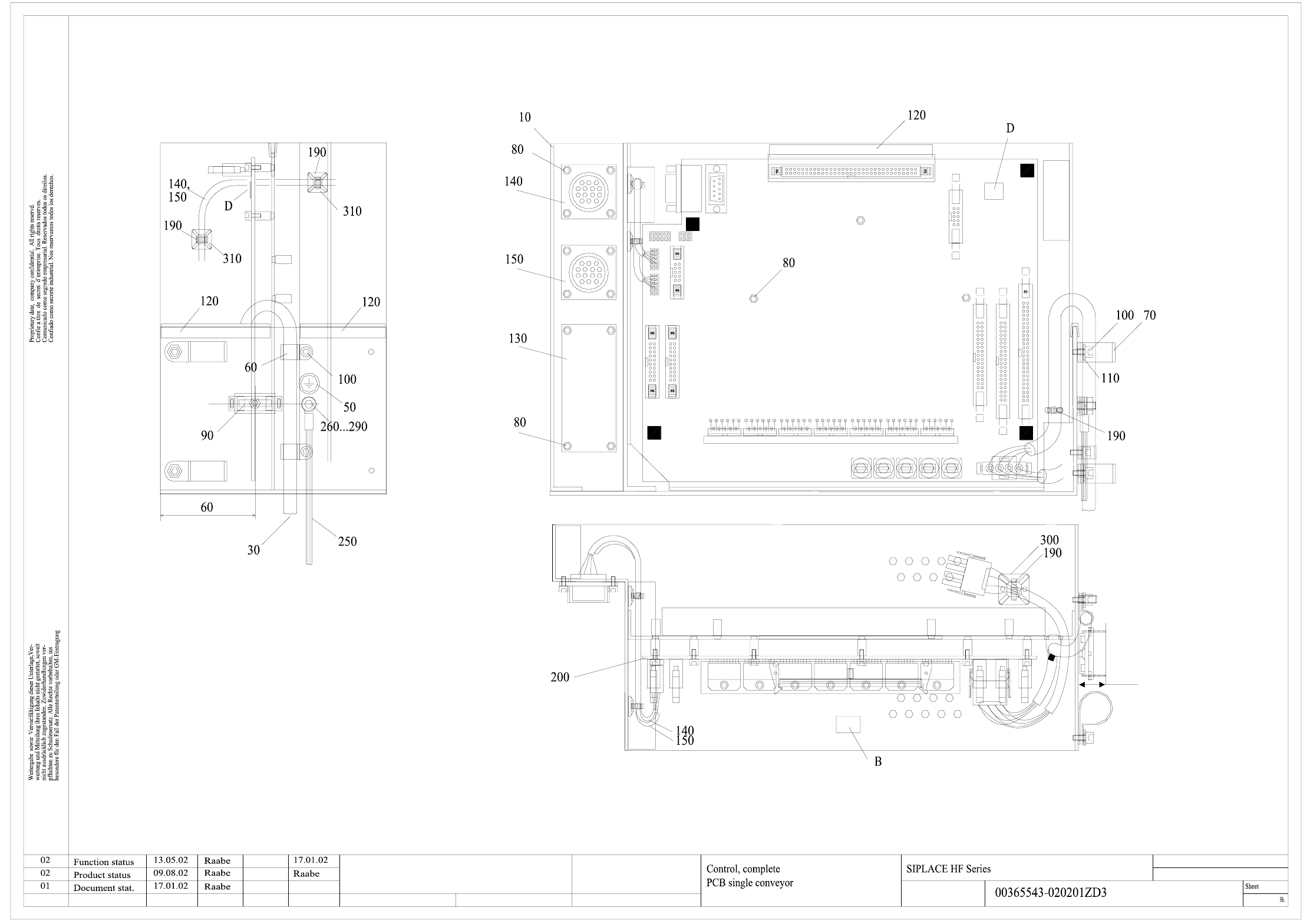
00365543-020201ZD3 Control complete, PCB single conveyor (Sh. 1 of 2)
B
D
Stand.
Check.
Author
Date
Status
Modified Date
Orig. Repl. f. Repl. by
2
1
Name
Ground connection according to
drawing 00343603-xx
Space for inspection label
Label for module identification "ao"
To be shortened
to 20+/-3mm
s
A&D EA
4 - 4
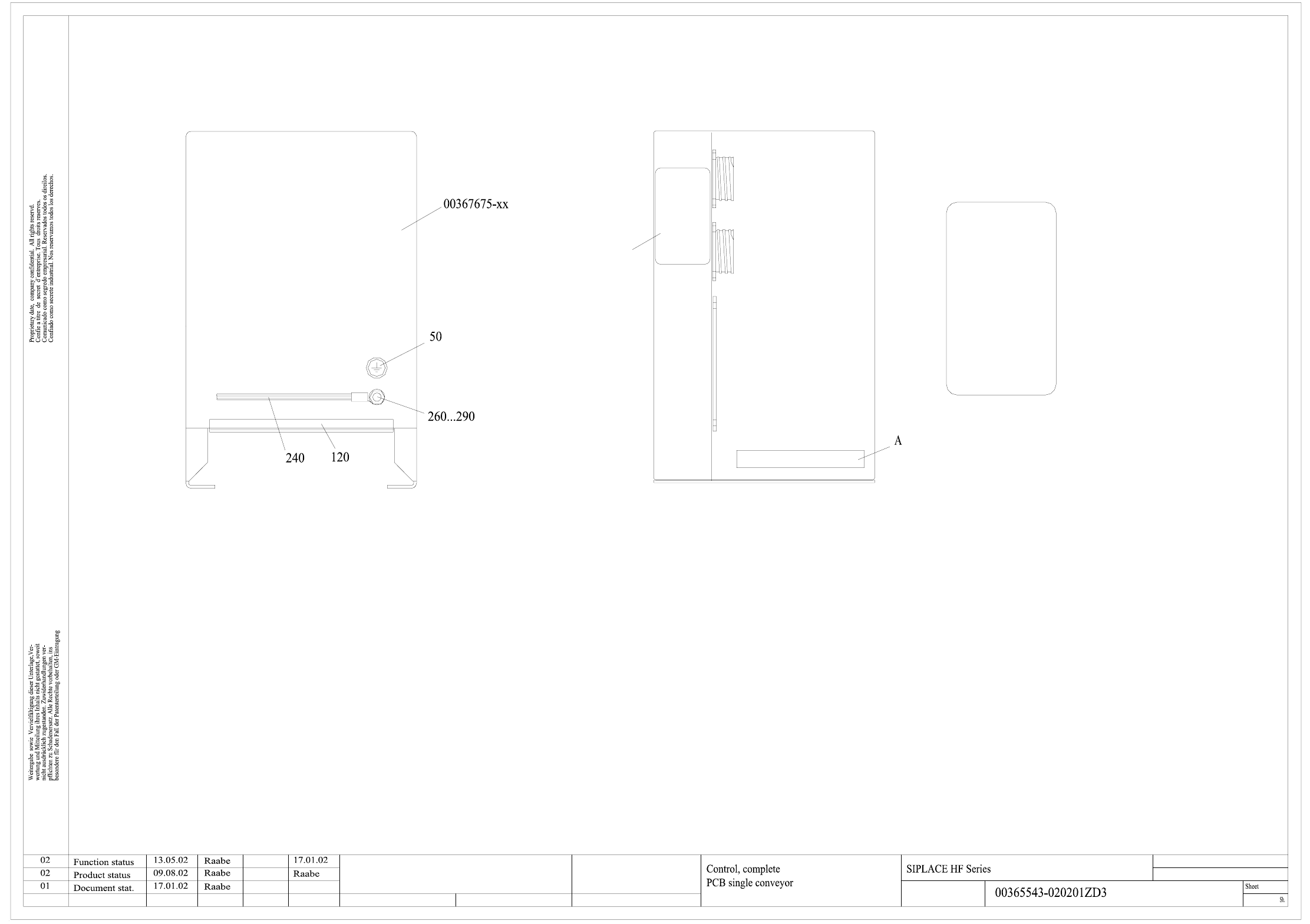
00365543-020201ZD3 Control complete, PCB single conveyor (Sh. 2 of 2)
A
Date
Author
Check.
Stand.
Status Modified NameDate
Orig. Repl. f. Repl. by
2
2
Label 1
drawing 00343603-xx
Ground connection according to
Vorgänger/
upstream station
SMEMA Interface
Spur 1 / track 1
Nachfolger/
downstr. station
Space for identification label
Label 1
Nachfolger/
downstr. station
SMEMA Interface
Spur 1 / track 1
Vorgänger/
upstream station
A&D EA
s